I finally got some time to assemble the ESP32-S3 dev boards we designed in this post.
I ordered a stencil with the PCBs - this is by far the easiest way to do SMD assembly at home.
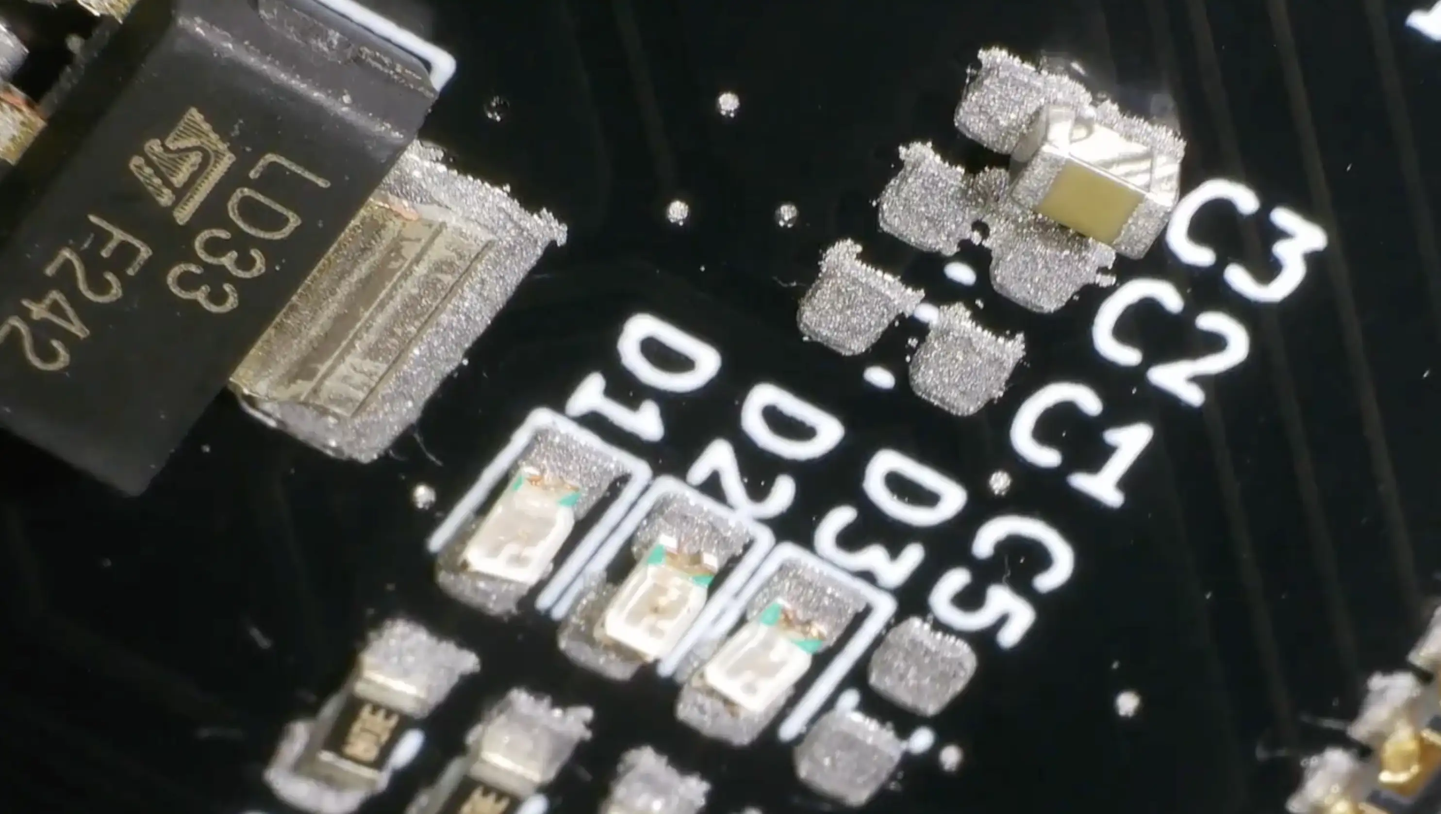
Solder paste is pretty forgiving, but I didn’t do a perfect job with this, so we did have some solder bridges on the USB pins. These are very fine pitch, so they often cause some problems.
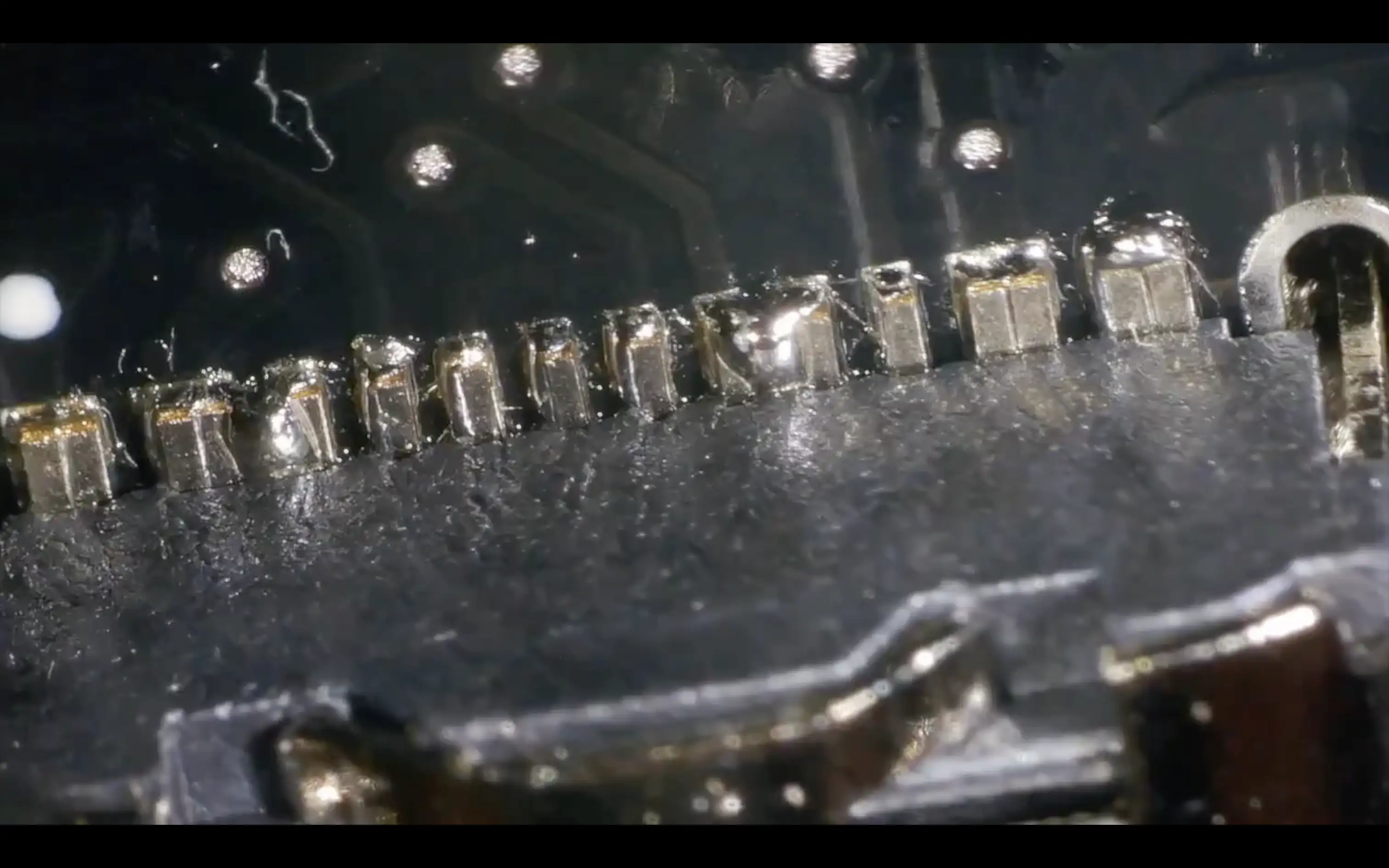
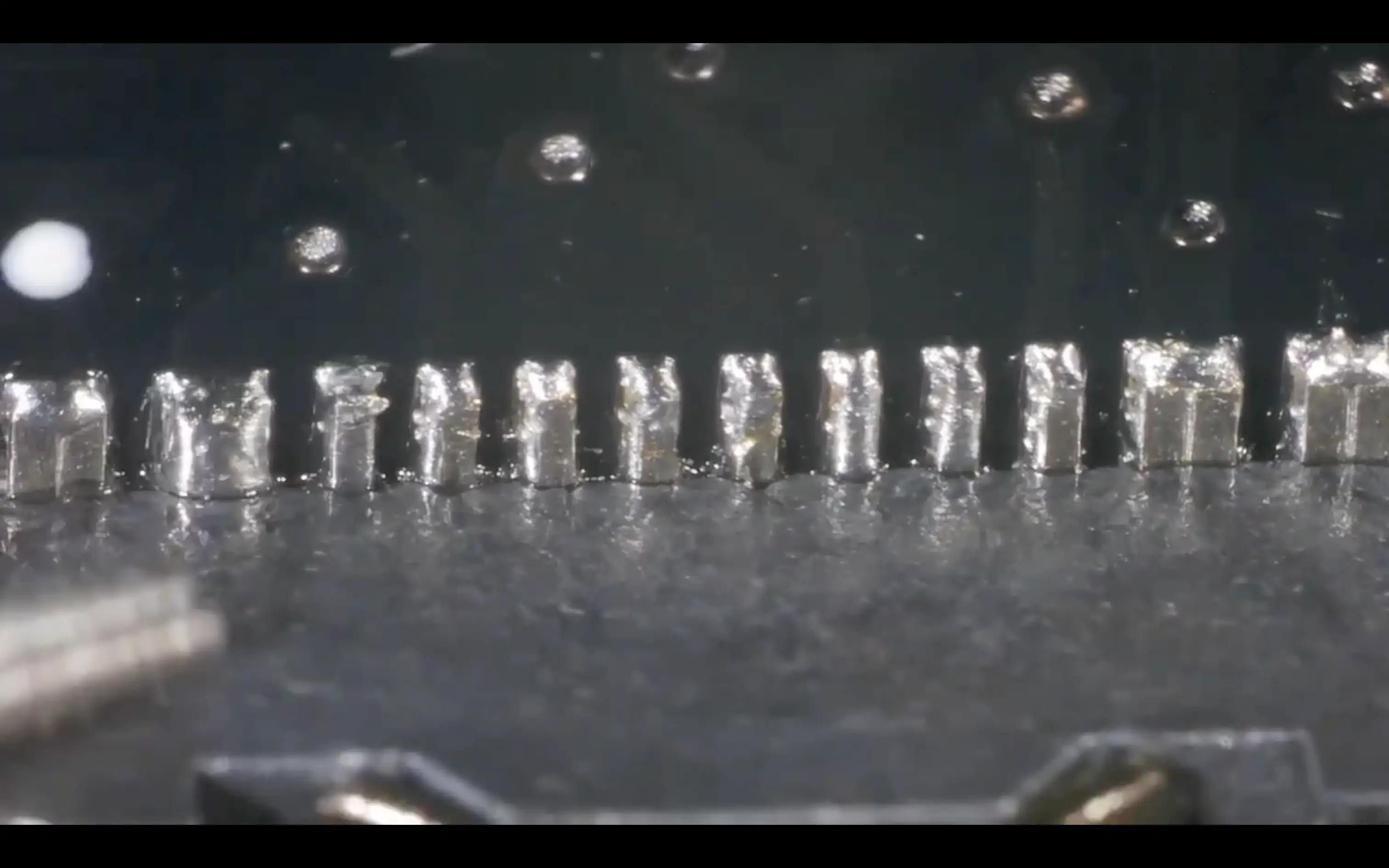
But a quick run over with the soldering iron and plenty of flux cleans them up without any problems.
I also did a hand-assembled version - there aren’t that many components on the board so this is pretty straightforward. One thing that is worth mentioning is that you don’t need to solder the EPAD. Connecting this does improve thermal performance, but the datasheet explicitly says it is not needed.

Plugging the board into USB gives us two LEDs - one showing we’ve got 5V coming in - and another showing that the 3V3 regulator is working.
You can easily check on a Mac to see if the device is working by typing the following command:
$ ls /dev | grep usb
cu.usbmodem1101
tty.usbmodem1101
You should see a couple of devices. For flashing, you may need to get the module into boot mode by holding down the boot button while pressing reset.
Flashing our board with a simple blink sketch works brilliantly.

You can watch the full assembly and walk through here.