View All Posts
read
Want to keep up to date with the latest posts and videos? Subscribe to the newsletter
HELP SUPPORT MY WORK: If you're feeling flush then please stop by Patreon Or you can make a one off donation via ko-fi
#DIY #ELECTRONICS #ESP32 #HARDWARE #MAKER #MICROCONTROLLER #MINIMALISM #PCB DESIGN

This post is also available as a video:

I’ve been designing an ESP32-based PCB recently, and I got to thinking - what’s the minimum you can get away with and still have a working module?

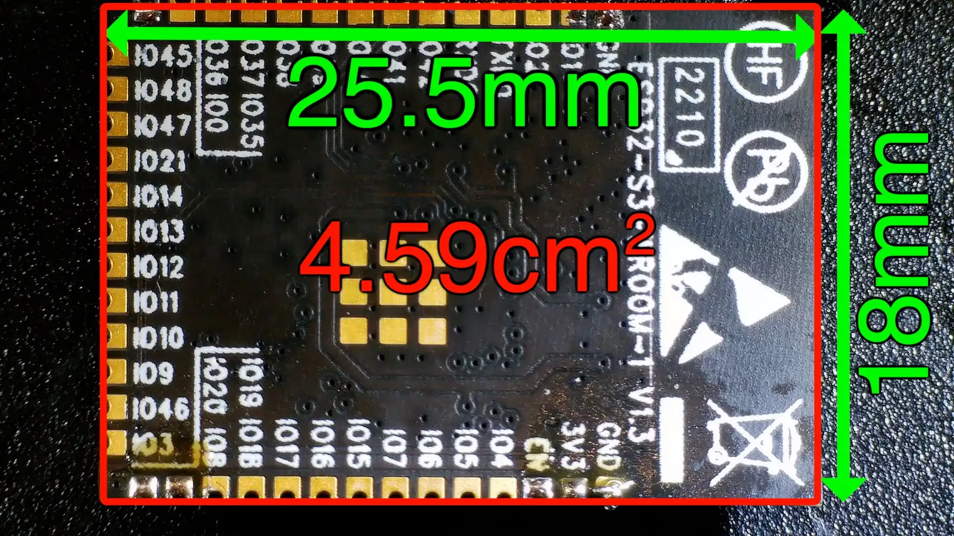
The ESP32 S3 WROOM module is particularly interesting. It only needs a few components to make a complete fully functioning dev board.

What’s nice about the S3 modules is that you don’t need to have a USB-UART bridge chip - you can connect it directly to the USB data lines.

But just how minimal can we make things and still have something that works?

Let’s have a look at the recommended schematic and see what we can chop out and what is required.

Schematic

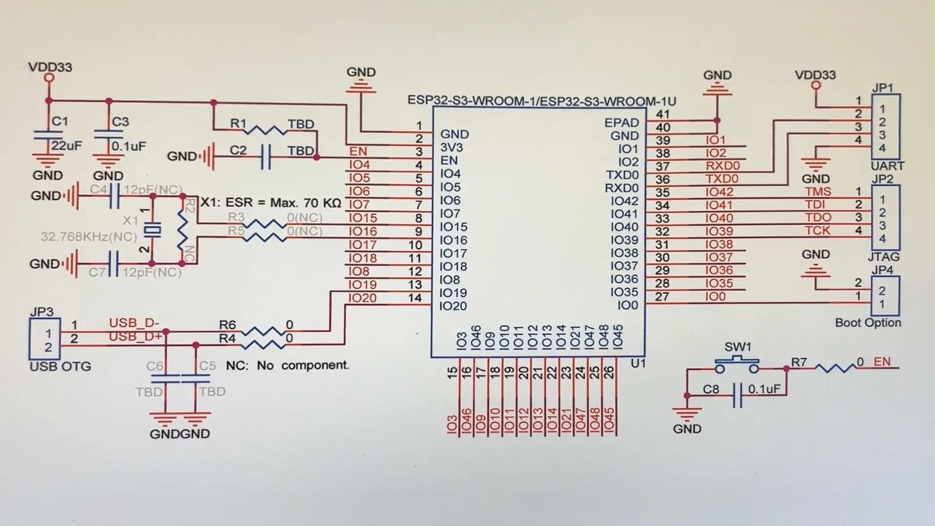
Something we definitely can’t do without is a ground connection, there are annoyingly two ground pins. We could probably just connect one, but I’ll hook up both to begin with.

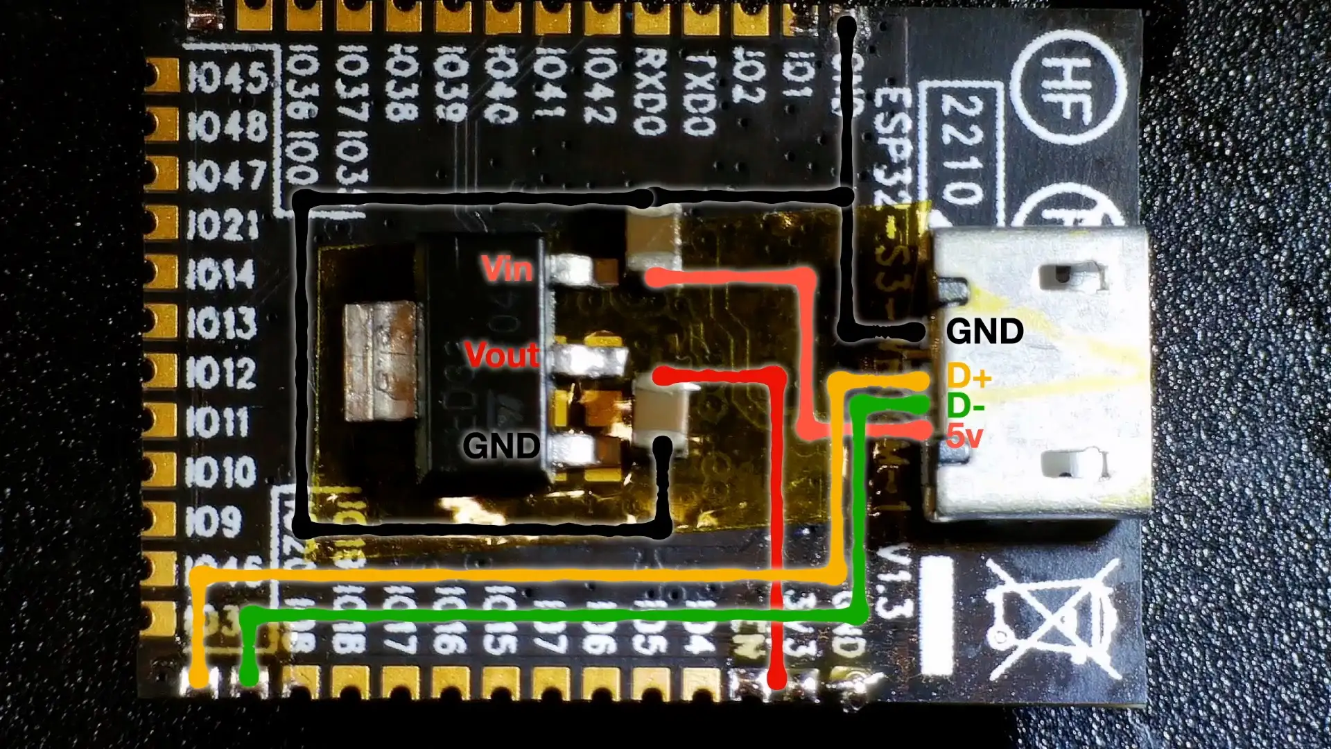
We’re also going to need 3.3 volts. Unfortunately, for this, we will need an external component - a voltage regulator - we get 5V out from the USB connection and if we use that directly it will fry our ESP32 (the ESP32 can take anything between 3.0 and 3.6 volts).

I’ve got a handy module that has an AMS117 3.3V regulator along with the required decoupling capacitors. So I’m just going to use that initially.

If we wanted to go even more minimal we could just drop the voltage over a few diodes to get it down to a safe level. Three diodes in series would get us down to around 3.2 volts which would be acceptable for an ESP32.

If it was a low-power device we could get away with a zener diode or even a resistor divider.

But the ESP32 can spike up to a lot of power - especially when you are using WiFi or Bluetooth.

Given that we’ve got some capacitors on the regulator board and we’re going to play fast and loose with this proof of concept, I’m crossing out the decoupling caps from the schematic.

For the enable pin we can just connect it directly to 3.3v. So we can ignore this little RC circuit. The recommended values are 10K and 1uF and it’s intended to stop the ESP32 from running until the supply voltage is stabilised.

Since we’re connecting directly to 3.3V we can also do away with the push button for resetting the device.

We can drop the crystal and capacitors - this is only required if you want to use an external oscillator for keeping accurate time in deep sleep.

The last thing we need is the data lines for the USB.

On the schematic there are a couple of zero-ohm resistors - so we can just ignore those.

There are also a couple of capacitors - these are optional, they can help with very noisy signals, but they aren’t required. So we’ll get rid of them as well.

IO19 goes to the D- pin and IO20 goes to the D+ pin.

If you’re using a brand new fresh module, you may need to connect IO0 to ground to manually put the ESP32 into download mode.

My experience is that you only need to do this the first time you program the module. However, your mileage may vary - it does seem to be quite fussy and the internet is full of people complaining that they can’t program their modules.

We can cross out this connection from the exposed pad to the ground - this is completely optional. It can help with heat dissipation from the module, but it’s not required.

I invariably get people commenting about how I’ve forgotten to solder this pad. So here it is direct from the datasheet:

Exposed Pad

And finally, we can cross out the UART connector - we’ll get our serial output over the USB connection. And we don’t need to use JTAG debugging, so that can go as well.

We’ve ended up crossing out a lot of the schematic.

What's left?

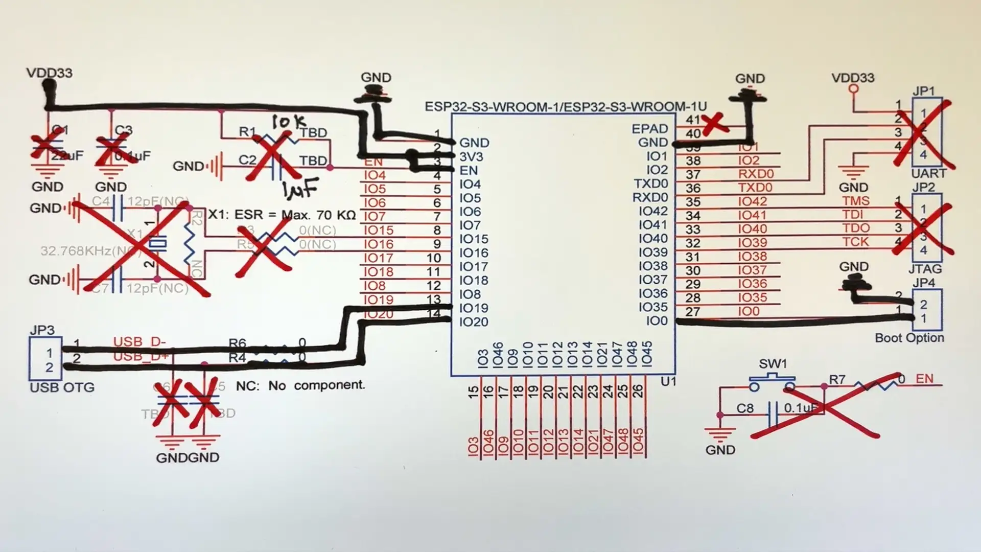
If we just draw what’s left we end up with this considerably simpler schematic.

Minimal Schematic

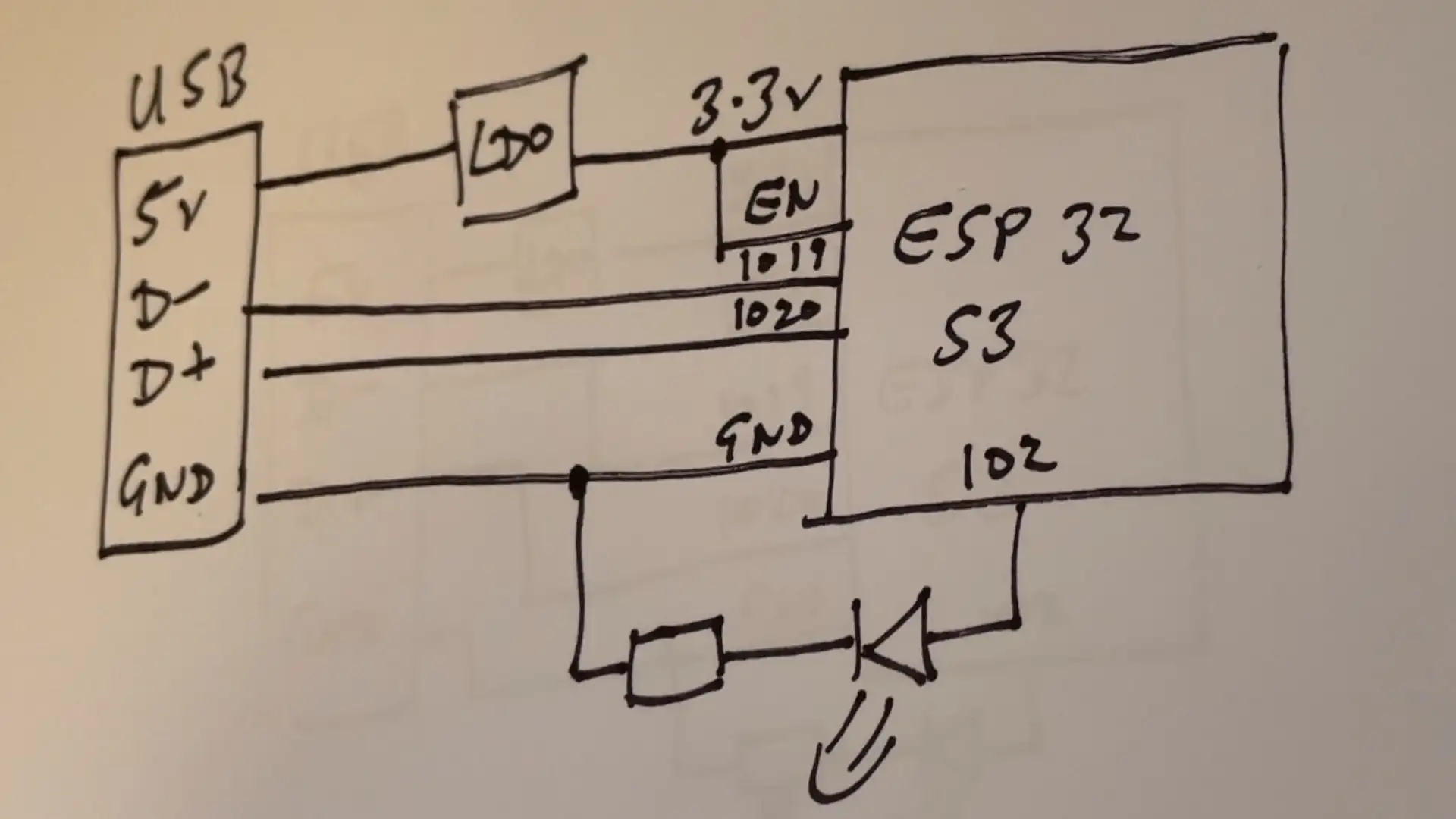
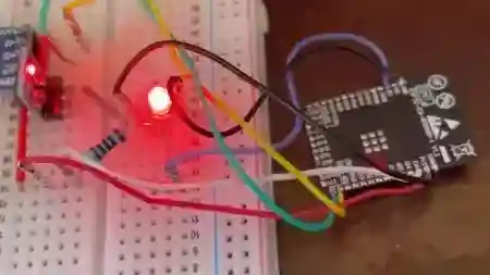
I’ve soldered some jumper wires to an ESP32-S3 module and hooked it up to a USB breakout board.

And… it’s flashing the LED! I was able to upload the blink sketch and it’s working perfectly.

Blink

The serial port is also working - though I did need to add these preprocessor definitions to get that working (I’m using PlatformIO - I’m assuming when using the ArduinoIDE this is not needed):

build_flags =
  -DARDUINO_USB_MODE=1
  -DARDUINO_USB_CDC_ON_BOOT=1

Now, at this point, most sensible people would call it a day - we’ve proved a point, we’ve shown you don’t need many components - very cool.

But not me, I got to thinking - there’s a surprising amount of space on the back of the module - we could probably fit the USB socket and the voltage regulator on it.

Lots of space

The circuit is not very complicated, how hard can it be? It’s just a few wires, surely we can hook everything up with small bits of wire and glue it all in place.

How hard can it be?

I covered up the EPAD with Kapton tape so nothing would get shorted and tried supergluing the components in place.

This kind of worked, but I struggled with the USB connector - firstly it just would not stick. And secondly getting in to solder the tiny pins just proved to be impossible for me.

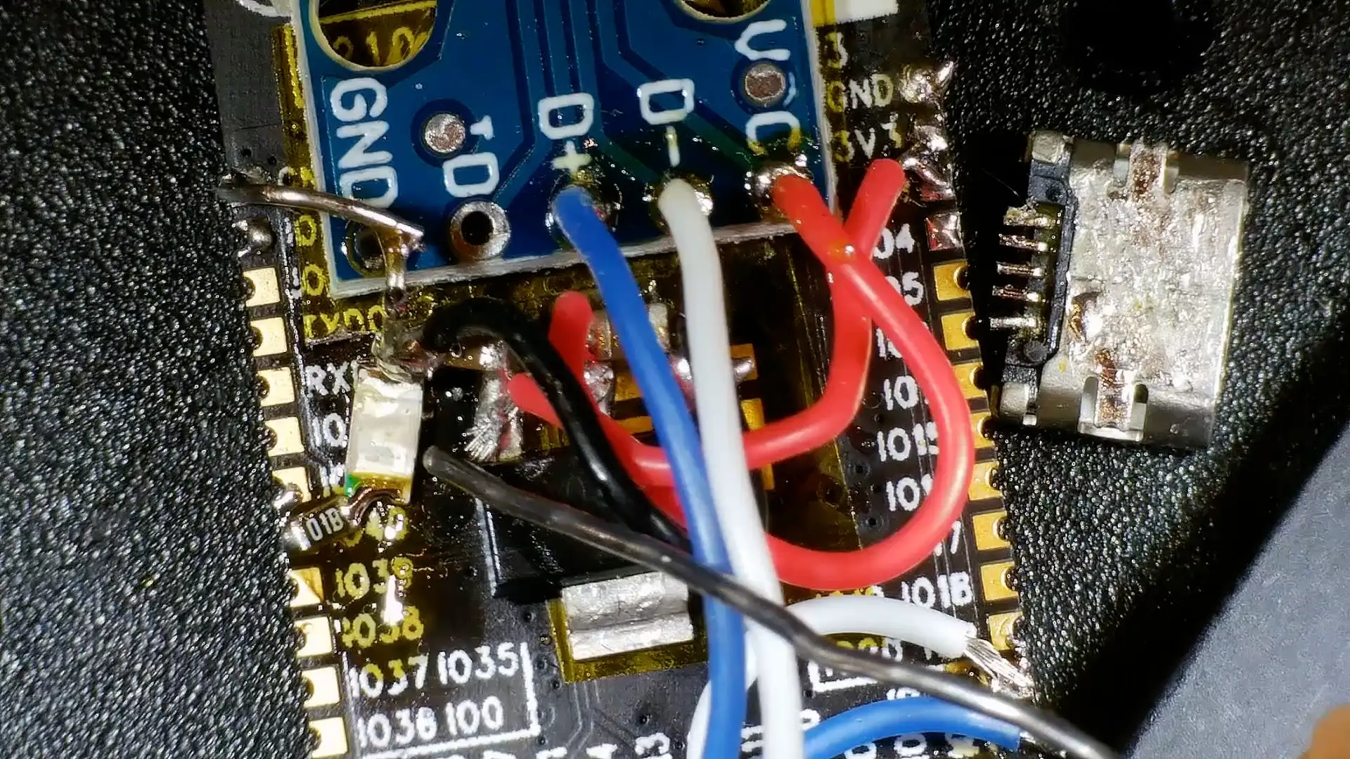
So I decided to swallow some pride and glued a USB breakout board in its place. This was a lot easier to solder the wires onto and it’s still pretty compact.

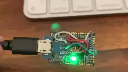
For the piece de resistance I added an LED to one of the more accessible pins.

It’s not pretty - the wires could be made much shorter and it’s a bit of a mess of solder and flux.

What a mess

But, it works! We can run our little blink sketch - amazing!

Blink Version 2

Would I do this again - probably not - but it was fun to try and see what was possible. There are also mini versions of the ESP32-S3 module. Not sure I’m quite up for that challenge though!

#DIY #ELECTRONICS #ESP32 #HARDWARE #MAKER #MICROCONTROLLER #MINIMALISM #PCB DESIGN

Related Posts

ESP32 TV Version 3 - In the latest board revision, I've successfully resolved some key issues, including a USB interface conflict between the USB2244 and the ESP32 and a risky battery charging mistake—no more direct USB 5V to the battery! Plus, I managed to wrap this up without any clumsy bodge wiring. I've even introduced a new feature: a microphone is now on board, setting the stage for some exciting future projects. Stay tuned for what's coming!
ESP32-S3: Which Pins Should I Use? - As an enthusiast of the ESP32-S3's versatility, I recognized the importance of understanding which pins are best to avoid. Inspired by the Random Nerds page for the classic ESP32, I've created a comprehensive pinout for the ESP32-S3 available on GitHub. The community's input is highly valued – suggestions and corrections are welcome to refine this resource into a dynamic guide for developers.
The PCBs are in production - what have I messed up? - After some stress and trepidation, I finally took the plunge and sent my PCB design off for manufacturing. My design centers around building a large seven-segment clock with LED filaments. Jumping hurdles such as voltages, pin usage, and limiting the load on my power supply, I've settled on the ESP32 as the system's heart and come up with a final circuit design. While doing this, I've quickly realized I could improve my layout and fixed a small mistake. Also, I've prepared for either types of LED filaments - the high-voltage ones or the larger, 3v ones. However, I did bungle up a couple of things on the enable line of the shift registers and board layout. But hey, this is a learning curve, right? Can't wait to get the boards and see what other exciting errors surface!
A Potentially Explosive Error - Just received the new PCBs for the ESP32-TV project and they're looking sharp with only a tiny resistor tweak needed. But I discovered a sneaky, undocumented resistor causing a conflict between the ESP32 and USB2244 over the USB connection. Fixed that, but there's a bigger issue lurking in the design - check the schematic in the video and see if you can spot it before I reveal the explosive mistake!
Look at my shiny crystal balls - Just upgraded my basic AliExpress crystal balls with some tech wizardry - I've thrown in an ESP32-S3-MINI, a mic, and made them battery powered. Thanks to WLED software, they're now smart and responsive! Shared the KiCAD project for fellow tinkerers. Check out my video to see these balls in action!

Related Videos

Minimalist Microcontroller: Building a Bare-Bones Dev Board - Dive into the fascinating process of building a minimal ESP32-based dev board, beginning with the ESP32-S3 Wroom module, and eliminating unnecessary components. Through soldering, wire connecting, and voltage testing, we reach a product that's compact, efficient and fully functional.
ESP32-S3 - Which Pins Are Safe To Use? - In this video, I've decided to dive deep into the ESP32-S3, a module ruling my lab recently due to its plug-in-and-play functionality, and the flexibility offered by its GPIO matrix. However, working with it requires vigilance, especially with regard to the strapping pins and USB data pins, among others. Discovering such quirks, I've encountered unexpected values, short glitches and the occasional code crash. To help you avoid these bumps, I've documented everything I've learned on my GitHub repo, where I'm inviting you, my fellow makers and engineers, to contribute your valuable experiences and findings. After a minor hiccup with my ESP32-TV, expect an updated PCB design, courtesy of PCBWay. Explore the ESP32-S3 with me, and let's unravel its secrets together, one pull request at a time.
Happiness is a Working Blink Sketch - ESP32-S3 PCBs Are Here! - In this video, I explore the functions of my newly arrived little boards - essentially a PCB that an esp32 S3 room module can be connected to. I put the board's voltage regulator, battery charger, and a 3 watt class D amplifier to the test, and damn, they work perfectly! I even use breadboards, connecting them together to facilitate a wider workspace. I gave the pcbs a spin, conducting sanity checks to ensure full functionality. With a successful battery charge and impressive voltage measurements, my PCB's are up to the challenge. I also dabble in some circuit jargon, explaining schematics, amplifiers, battery chargers and a clever mosfet approach. To top it off, I solder on an ESP32 module and prove that yes, it actually works. Stay tuned for a following video where we'll work with a speaker and display!
Lots of Stuff - And a NEW PCB! It's a rare mailbag video. - In today's episode, I'm unboxing some goodies from PCB way - my super tiny esp32 breakout boards, which I'm planning to use to recreate a mini TV complete with speakers and a display. Also received some convenient adapter boards for easier testing. Excited to explore a new Arduino Nano esp32 based on a different, tinier module, and contrasting it with other products like the Tiny Pico. Also up for testing is a new mini wear electronic load compared to my old one, and an ATX power adapter for more USB ports. I'll be testing power banks, playing with inexpensive yellow displays and nunchucks for fun gaming projects, and testing out an RGB bead curtain with hackable possibilities. Also, under my ongoing experiments is a Raspberry Pi zero, turning into a 'Doom' playing device with added sound and game controllers. Finally, an air quality measuring device for detecting air particles, CO2 levels, humidity, temperature and other parameters is up for exploration as well. A whole array of fun projects queued up, so stay tuned!
We don't need a DAC - ESP32 PDM Audio - In this video, I've made some fascinating explorations with the ESP32 S3 chips and TinyS3 boards from Unexpected Maker. Intriguingly, even without a DAC converter, S3 chips can produce an audio waveform. I've played around with a basic RC filter to reconstruct the analogue audio signal from a PDM signal. The result was quite impressive for a board without a native DAC! I also discussed the possibility of creating a simple amplifier using just a MOSFET as a switch. Finally, I gave a peek into some of my new boards from PCBWay and looked at how Delta Sigma modulation can be played with to recover original data. It's all quite a fun foray into the world of circuitry and audio signals!
HELP SUPPORT MY WORK: If you're feeling flush then please stop by Patreon Or you can make a one off donation via ko-fi
Want to keep up to date with the latest posts and videos? Subscribe to the newsletter
Blog Logo

Chris Greening


Published

> Image

atomic14

A collection of slightly mad projects, instructive/educational videos, and generally interesting stuff. Building projects around the Arduino and ESP32 platforms - we'll be exploring AI, Computer Vision, Audio, 3D Printing - it may get a bit eclectic...

View All Posts