🌈 ESP32-S3 Rainbow: ZX Spectrum Emulator Board! Get it on Crowd Supply →
View All Posts
read
Want to keep up to date with the latest posts and videos? Subscribe to the newsletter
HELP SUPPORT MY WORK: If you're feeling flush then please stop by Patreon Or you can make a one off donation via ko-fi
#DATASHEET DEEP DIVE #ELECTRONICS #EMBEDDED AUDIO #ESP-IDF #ESP32 #FIRMWARE #HARDWARE DEBUGGING #I2S #OSCILLOSCOPE #PCB DESIGN #PDM MICROPHONE #STEREO

In the last post we were testing out the audio on my new board. There something in the code that piqued my interest.

We’re using a standard I2S PDM microphone - which has the normal pins you’d expect for I2S.

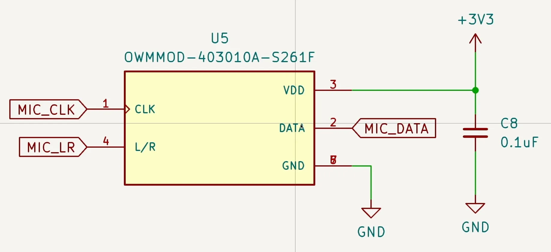
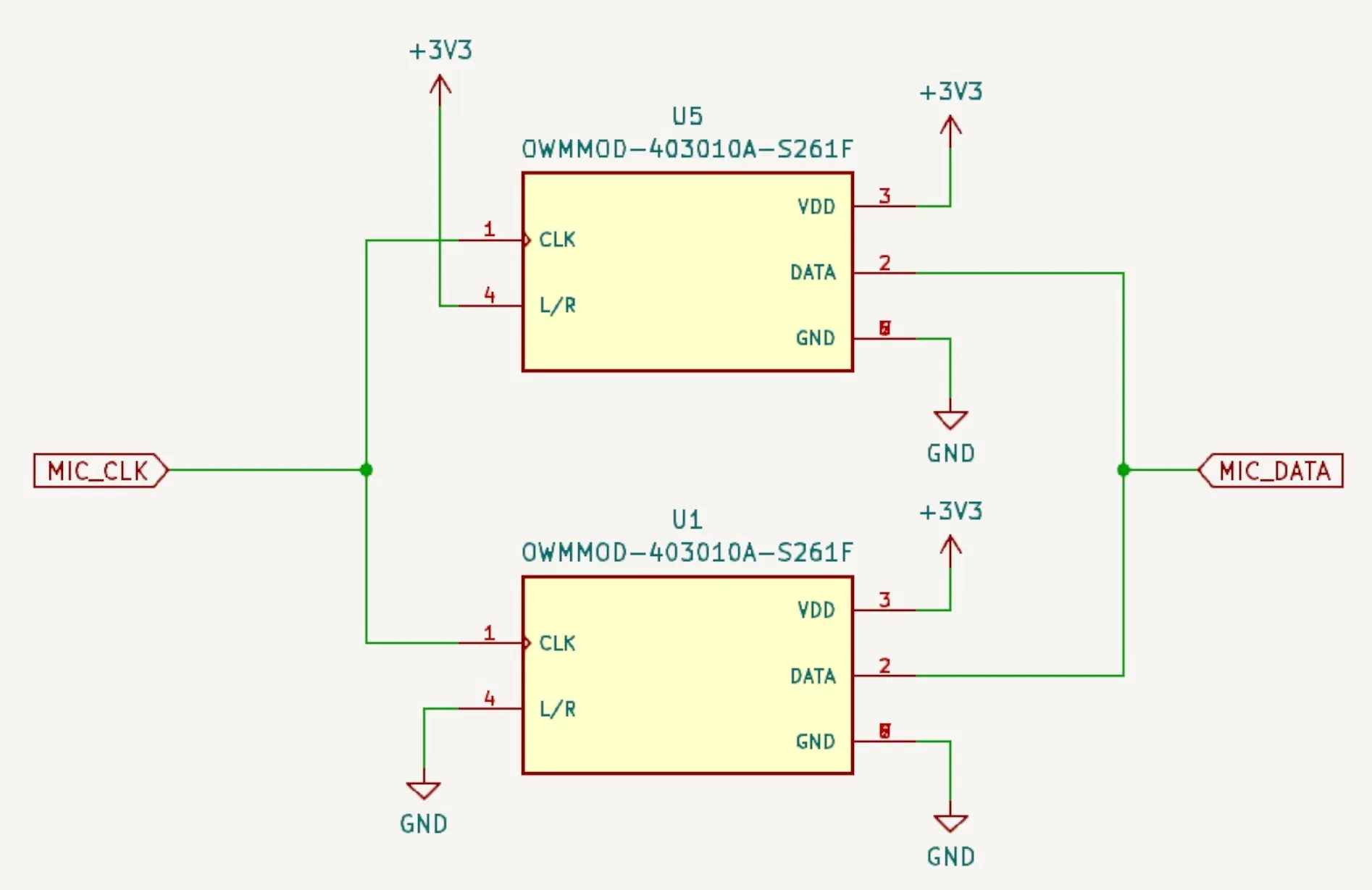
Here’s my schematic:

The Schematic

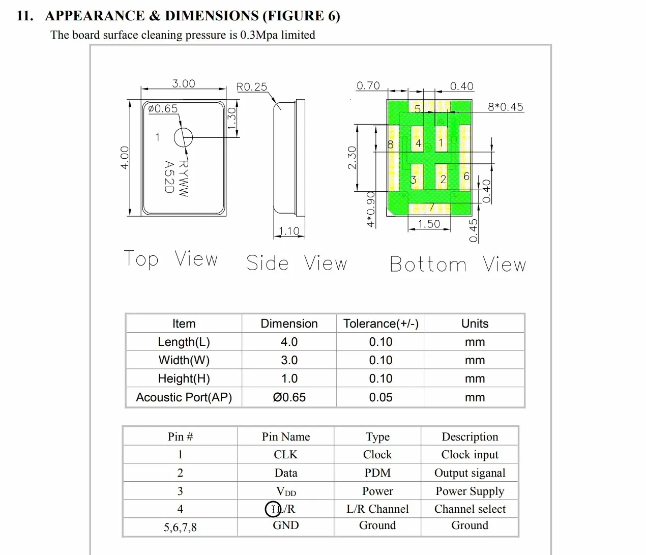
And here’s the datasheet to confirm I haven’t made a silly error:

The data sheet

You’re probably thinking - yes yes, all very interesting, that’s the standard pins for I2S - CLK, Data, L/R and power.

Well, what confused me was the I2S code in the latest ESP-IDF version.

What about the LR pin?

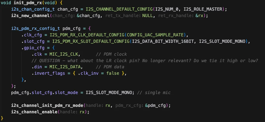
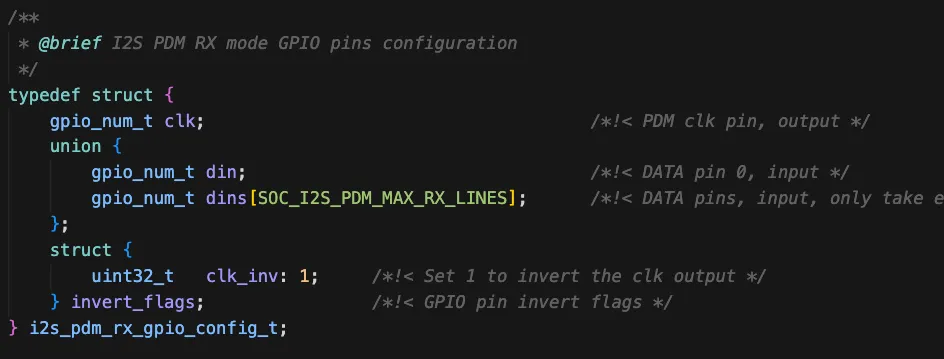
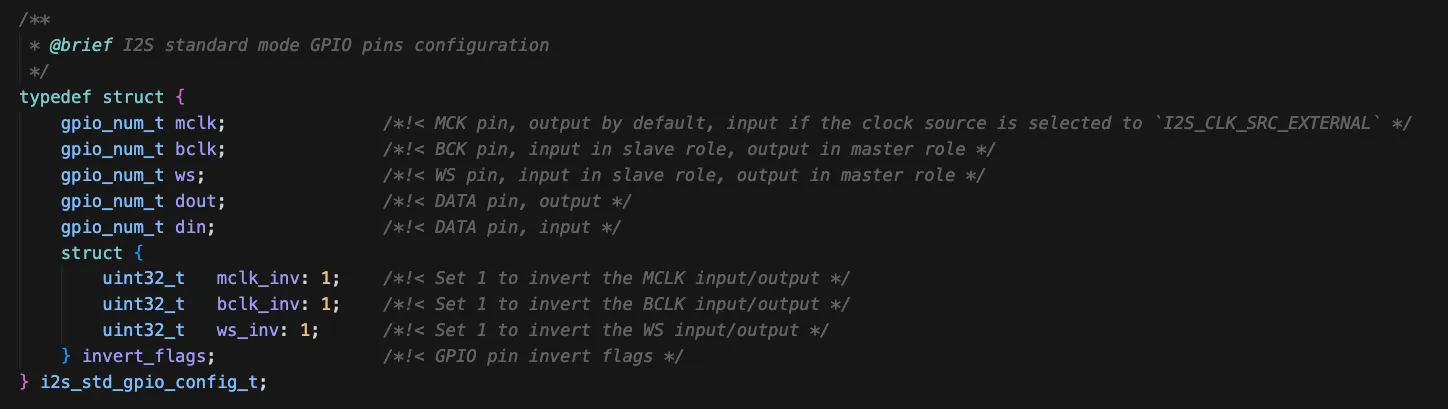
There is no way to specify the LR pin! The gpio_cfg structure for PDM microphones doesn’t have an entry for it.

It’s not here!

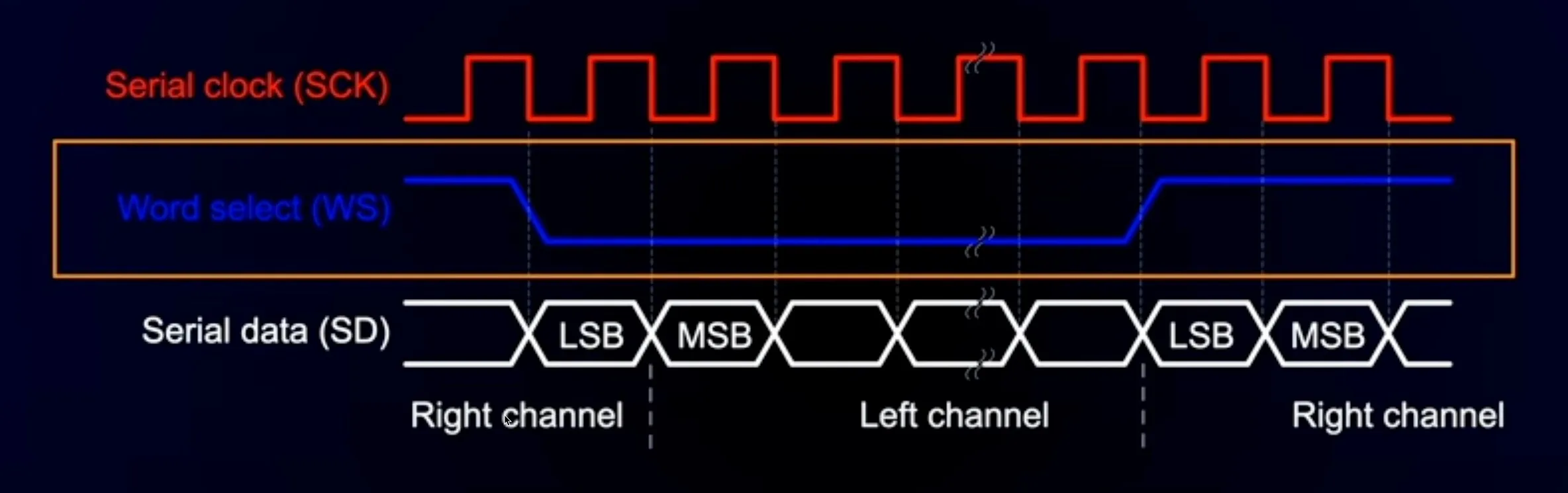
For PCM microphones the LR clock is pretty important - particularly if you want to have a stereo signal.

Looking back at one of my ancient YouTube videos you can see the waveforms:

PCM Signals

And if we look at the structure used to initialise I2S for PCM the pin is definitely there.

There’s an LR pin here!

So, what’s going on with PDM microphones? What are we supposed to do with the LR pin?

A quick question to the ESP32 forums set me straight with a very friendly - look again at the data sheet for your microphone.

And looking a bit more closely we find these example IO timing diagrams:

Look at the data sheet properly…

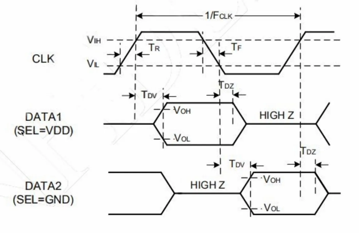
If the LR pin is held high - the data is valid for the high to low transition of the clock and then the data pin goes high impedance.

If the LR pin is held low - the data is valid for the low to high transition of the clock and then the data pin goes low impedance.

This means that if you want to have two microphones (for stereo recording) you just need to tie one high and one low - and they will happily coexist on the same data line.

Stereo PDM microphones

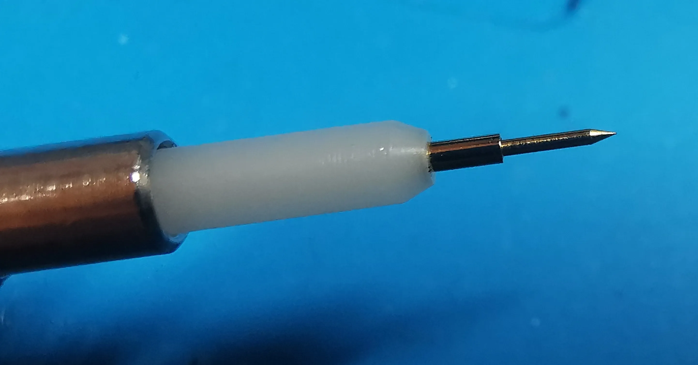
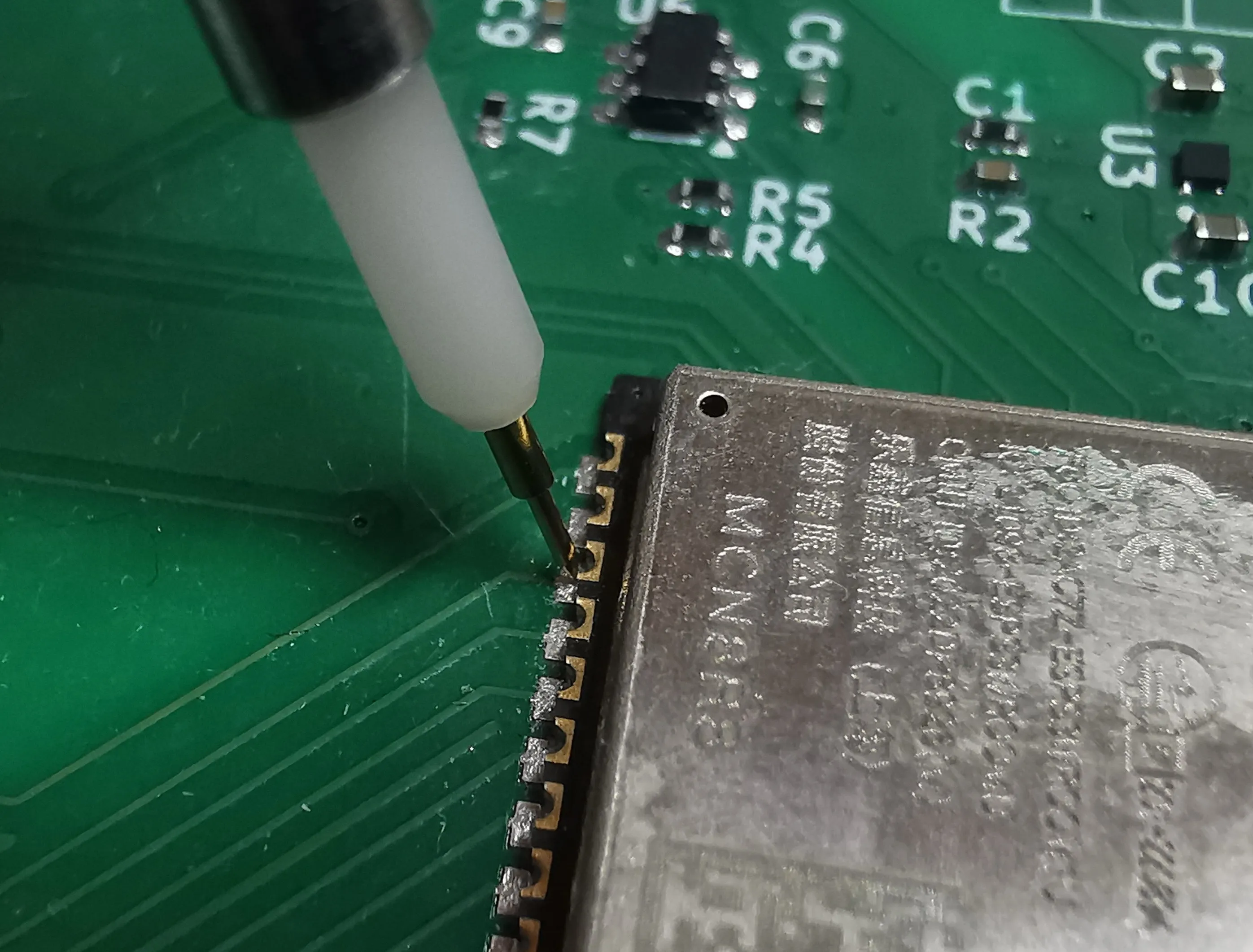
I’d recently purchased some fancy probes, so I decided to check this out.

Nice probes!

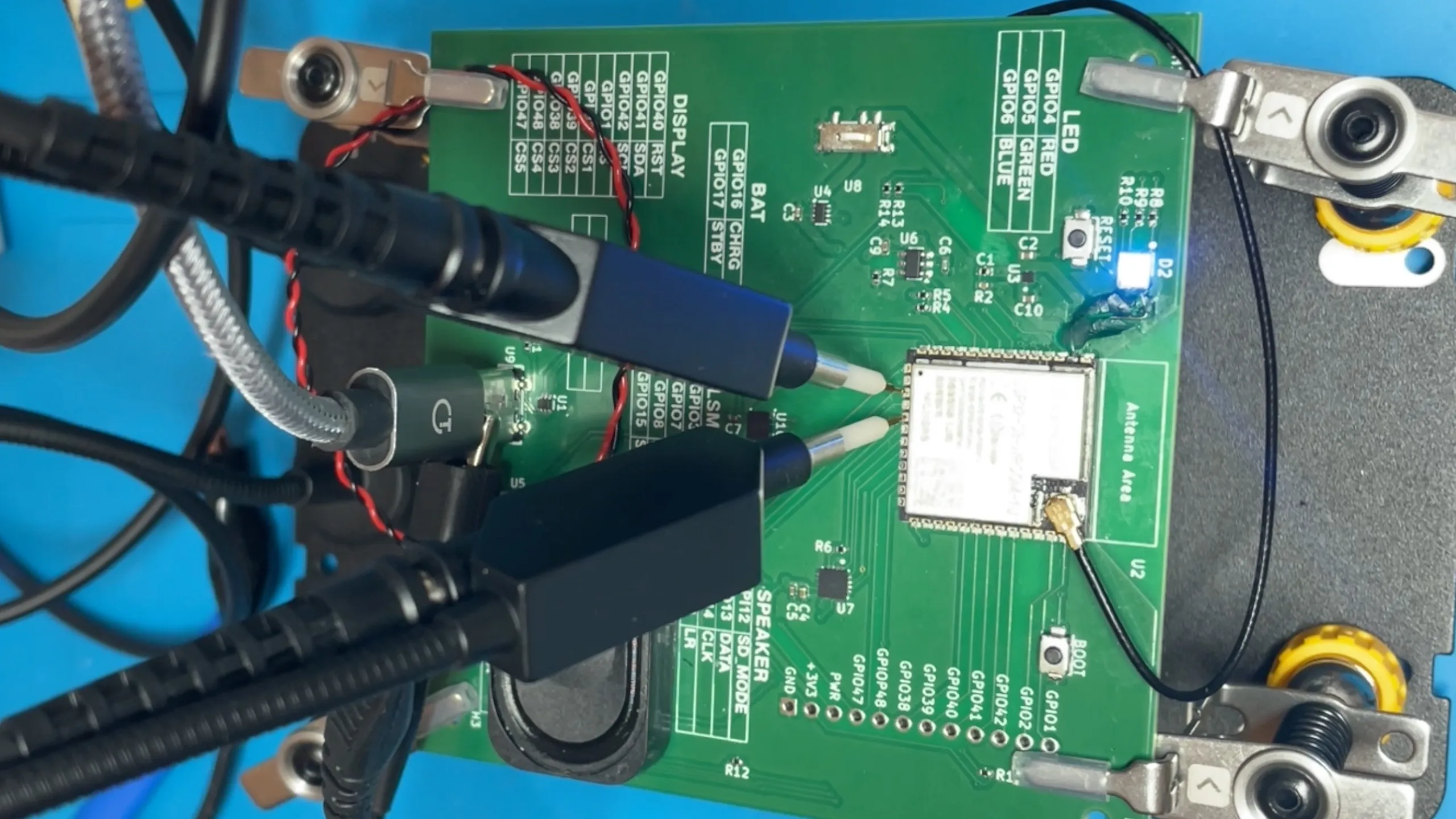
These are really nice - they have a pogo needle on the end so you can get into very small places on the PCB. They are also hands free. Pretty cool - you can pick up you own set here (affiliate link!).

Needle point

Probing the PCB

I monkeyed around with the code a bit and changed the data pin so that it had a pull down resistor and made it so I could toggle the LR pin between high and low.

Here’s what we see when the LR pin is held low:

LR = GND

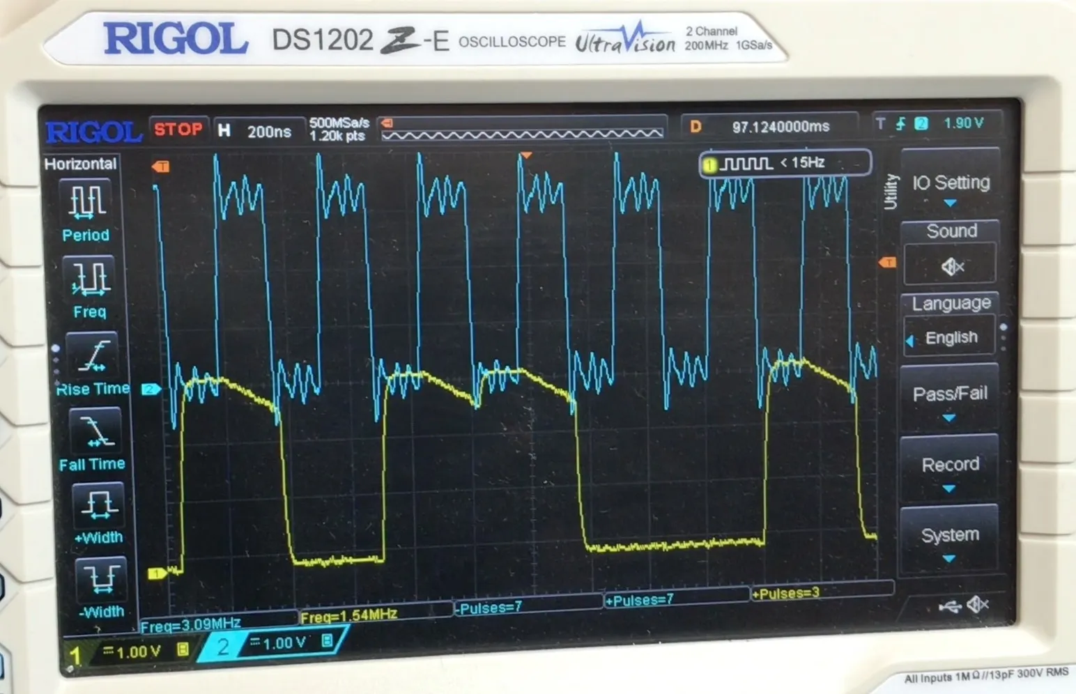
And here’s what we see when the LR pin is held high:

LR = VDD

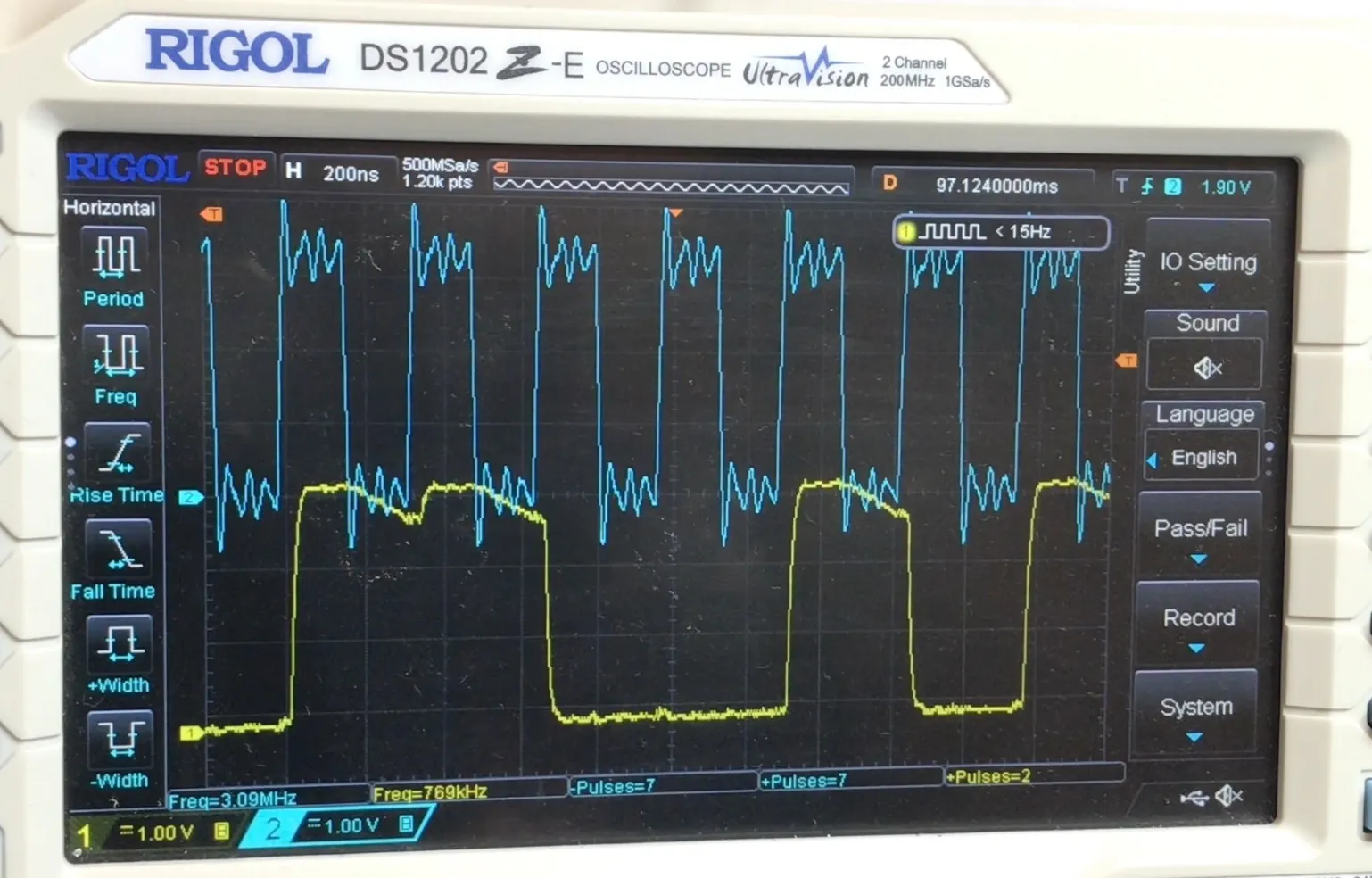
Hopefully you can see the difference. With the LR pin low, the signal starts to decay when the clock is high, and with the LR pin high, the signal starts to decay when the clock is low.

We’ve only got the internal pull down resistor pulling it down so it doesn’t go to zero that quickly. If there was another microphone driving the pin then it would fall straight to zero if needed.

So, all in all pretty interesting. One thing that is quite useful is that we don’t need to connect the LR pin to a GPIO - we can save a pin in our next design!

#DATASHEET DEEP DIVE #ELECTRONICS #EMBEDDED AUDIO #ESP-IDF #ESP32 #FIRMWARE #HARDWARE DEBUGGING #I2S #OSCILLOSCOPE #PCB DESIGN #PDM MICROPHONE #STEREO

Related Posts

E32-S3 no DAC - No Problem! We'll Use PDM - In this post, I tackle the lack of a DAC on the ESP32-S3 by demonstrating how to use Pulse Density Modulated (PDM) audio with Sigma Delta Modulation to achieve analog audio output. I explore the simplicity of creating a PDM signal and its reconstruction into an audio signal using a low pass filter, even an RC filter, though a more sophisticated active filter is recommended. I guide through using both a timer and the I2S peripheral on the ESP32 for outputting PDM data, noting the quirks and solutions for each method. And I wrap up with how straight PDM signals can drive headphones or work with various amplifiers, including the MAX98358 or SSM2537, exhibiting the versatility of PDM in audio applications with the ESP32-S3.
ESP32 Audio Input - MAX4466, MAX9814, SPH0645LM4H, INMP441 - In this blog post, I've delved deep into the world of audio input for ESP32, exploring all the different options for getting analogue audio data into the device. After discussing the use of the built-in Analogue to Digital Converts (ADCs), I2S to read ADCs with DMA, and using I2S to read directly from compatible peripherals, I go on to present hands-on experiments with four different microphones (MAX4466, MAX9814, SPH0645, INPM441). This comprehensive look at getting audio into the ESP32 should be a valuable resource for anyone hungry for a deep-dive into ESP32's audio capabilities, complete with YouTube videos for an even more detailed look!
ESP32-S3 USB UAC - I turned my new ESP32‑S3 board into a USB Audio device. After a ninja LED fix and confirming the IMU and charging, I streamed mic audio over Web Serial (with a slick AI-made ‘Audio Studio’) and then via USB UAC. The mic sounds great, but the speaker is crackly over UAC—even though I2S WAV playback is perfectly clean. ESP-IDF worked; Arduino didn’t. Bonus annoyance: macOS vs Windows is a toggle, not a combo. Still, this board passes QA.
Connecting up the MCP23S17 and HD44780U based LCD - Ever wondered how to hook up an LCD display with your Raspberry Pi without using up all your GPIO pins? With the right tools, such as the MCP23S17 and wiringPi, you can effortlessly keep your I2C, UART, and SPI functionalities free for other worthwhile endeavors. This blog post truly proves that the GPIO is quite flexible with the I2C or SPI pins and setting up the MCP23S17 is as simple as connecting the pins. And with support for 5v LCD modules, I can assure you that this setup is definitely lit!
I broke it and then i fixed it - Started off on a techie adventure with an RP2040 DVI board from Adafruit, aiming to get the pico-zxspectrum going. Things started acting haywire once the USB hub got involved, ending in a complete shutdown, intuitive diagnosis showed the power pin was a ghost town! After pin-pointing (and removing) the dead IC, I performed a delicate soldering operation to bless it with a new 3V3 regulator. Working the kinks out with the resolution led to a thrilling revival and, voila, we were back in business with DVI output and SD Card support!

Related Videos

ESP32 PDM Microphone - What do you do with the L/R pin? - I treated myself to some hands-free probes and dug into the PDM mic on my ESP32 board. I was confused that the new I2S PDM API only asks for clock and data—no LRCLK—yet the mic datasheet shows an LR/SEL pin. The trick: in PDM, LR is just a static select. Tie it low and data is valid on the rising edge; tie it high and it’s valid on the falling edge, so two mics can share the same I2S lines by picking opposite polarities. I proved it on the scope and realized I don’t need to burn a GPIO on LR at all—just hard-wire it high or low and save a pin.
ESP32-S3 USB UAC Audio Device - does it work? - Time for an audio project: I took my PCBWay ESP32‑S3 board for a spin—fixed the common anode/cathode LED mix‑up, verified the IMU and battery charger, then tested an I2S PDM mic and tiny speaker with a Web Serial Audio Studio (scope, spectrogram, tuner). I also turned it into a USB UAC device in ESP‑IDF: the mic is clean, but speaker over UAC is crackly (Mac/Windows toggle oddity); direct I2S WAV playback is perfect, so the hardware passes QA.
ICS-43434 A replacement for the old INMP441 - Ideal for the ESP32 - Learn how to use the latest ICS-43434 I2S MEMS microphone for your audio projects and get insights on the PCB design process, including circuit diagrams and layout!
ESP32 Audio Input Showdown: INMP441 vs SPH0645 MEMS I2S Microphones! - Discover the performance of two MEMS microphone boards, the SPH0645 and the INMP441, when connected to an ESP32. This video showcases their audio recording capabilities, noise handling and overall usability, with the INMP441 emerging as the winner!
Super Easy ESP32-S3 Dev Board - Making an ESP32-S3 dev board is way easier than it looks. I simplify the datasheet reference: skip the external crystal, wire native USB D+/D− (pins 19/20) straight to a USB-C with 5.1k CC pulldowns, add a BOOT switch and an EN RC reset, and power it with an LD117 LDO that’s happy with ceramic caps. In KiCad I build the schematic with Espressif libraries, add LEDs for 5V, 3V3, and a blink GPIO, set up net classes, route a clean USB differential pair, stitch a solid ground plane, and label everything. It’s a bit wide—just gang breadboards together—and you end up with a neat, professional S3 dev board you can flash and debug over USB.
HELP SUPPORT MY WORK: If you're feeling flush then please stop by Patreon Or you can make a one off donation via ko-fi
Want to keep up to date with the latest posts and videos? Subscribe to the newsletter
Blog Logo

Chris Greening


Published

> Image

atomic14

A collection of slightly mad projects, instructive/educational videos, and generally interesting stuff. Building projects around the Arduino and ESP32 platforms - we'll be exploring AI, Computer Vision, Audio, 3D Printing - it may get a bit eclectic...

View All Posts