I was doing some experiments with a small infrared thermal sensor module — an MLX90640, 32×24 pixel IR camera that talks over I²C.
This was meant to be a quick test before moving on to a larger project.
It did not go to plan.
The Symptom: Nothing on I²C
When I first plugged the module in, it simply didn’t respond at all.
- No data
- No errors
- No sign of life
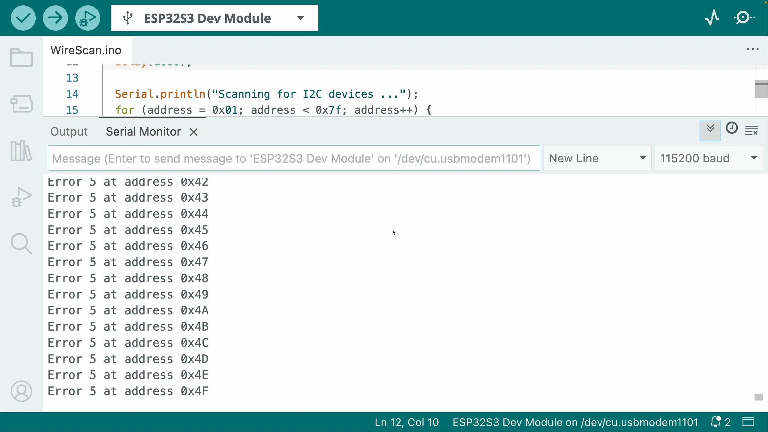
An I2C scan showed nothing connected. You can easily run an I2C scan in the Arduino IDE - it’s one of the demos for the Wire library.
The Usual I2C Suspects
I went through all the standard checks:
✅ I2C Address Scanning
I ran the I2C scanner to see if the device appeared at any address.
Normally, when nothing shows up, there are three things to check:
- Pull up resistors - do you need them?
- Wiring - have you got SDA and SCL swapped over?
- Power issue - are you actually powering the device? Does it take 3V3 or 5V?
✅ Pull-Up Resistors
I²C needs pull-ups on SDA and SCL, so I checked:
- Are pull-ups present on the board?
- Does enabled the built in ESP32 GPIO pull ups make any difference?
- Does adding external ones help?
Some modules include pull-ups, some don’t. Sometimes you can get away with the internal GPIO pull-ups. Sometimes you need stronger ones.
I tried everything!
✅ 5V vs 3.3V Logic
Originally, Arduinos used 5V logic. A lot of “Arduino Compatible” modules include a 3V3 regulator so they can be powered from 5V.
This can cause some issues if you try and power the modules off 3V3 - the LDO that are used can have a surprisingly high drop out voltage (the classic AMS117 can drop 1.2V!). This can cause the boards not to function, or to behave quite eratically.
I tried both 3V3 and 5V - no joy!
✅ Wiring
The other classic is just incorrect wiring. It’s very easy to get SCL and SDA swapped over, or misread the pins you’ve connected to.
It’s also possible that you may get unlucky and pick some pins that are being used for something else - particularly on dev boards that have a lot of built in peripherals.
I tried everything, different pins, different cables, the works.
My first schoolboy/girl error…
Eventually I noticed something embarrassingly obvious.
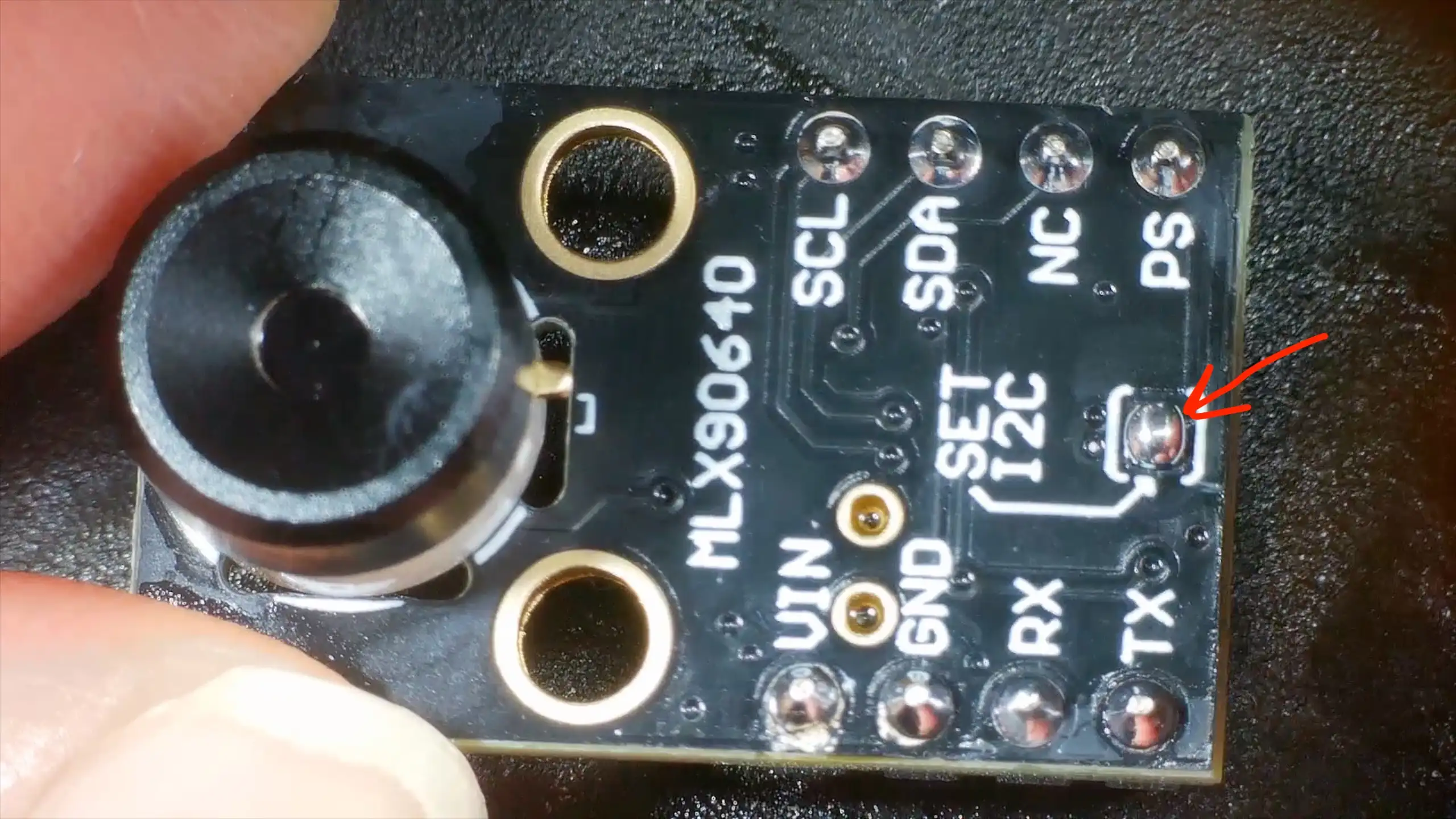
This module has a small solder jumper that selects I2C mode.
I’d forgotten to add a blob of solder to it - my module was in UART mode! Problem solved I thought to myself!
…still nothing.
The Actual Problem: Bad Soldering
At that point, I stopped assuming the board was electrically sound and put it under the microscope. To be honest, I’d come to the conclusion that my board was DOA and I’d have to ask for a refund.
But, the microscope does reveal all.
Some of the pins on the module’s 3V3 LDO did not look properly soldered.
They looked fine at a distance, but under magnification looked pretty dodgy.
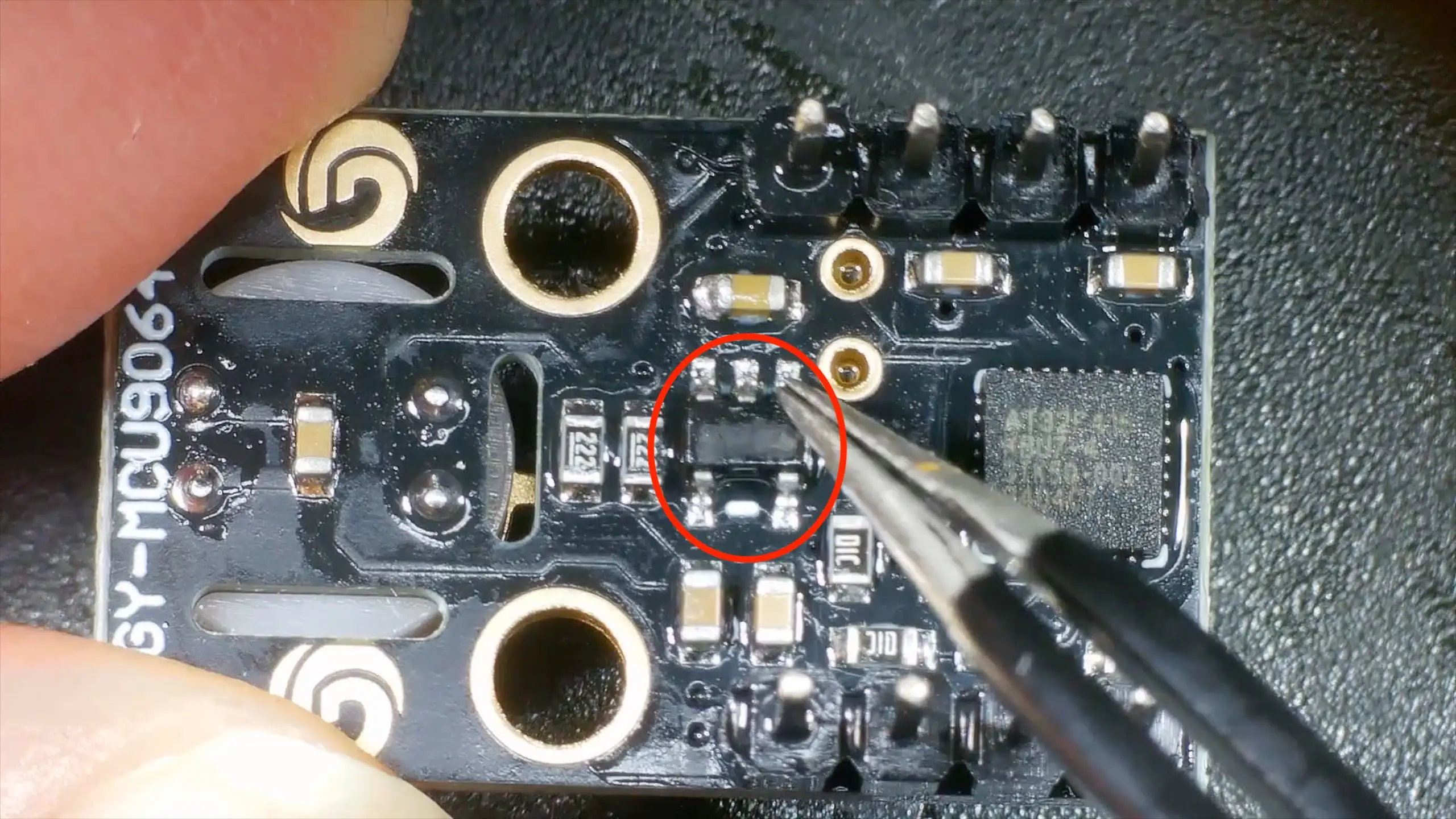
The Fix
I reflowed the joints and everything sprang into life. I2C address scanning found the module and a test program started reading temperatures from it!
Lessons Learned (Again)
This is one of those lessons you know, but still relearn regularly:
🔧 Don’t Trust Factory Soldering
Especially on:
- Cheap breakout boards
- Modules from unknown vendors
- Very fine-pitch ICs
🔍 Look Early, Not Late
If something:
- Doesn’t respond at all
- Isn’t visible on I²C
- Shows zero electrical activity
…get the microscope out sooner rather than later.
🧠 Software Isn’t Always the Problem
If you’ve:
- Checked wiring
- Checked voltages
- Checked pull-ups
- Checked addresses
It’s probably time to assume hardware.
Coming Up Next
Now that the module is actually working, I can get on with the real project that uses it.