🌈 ESP32-S3 Rainbow: ZX Spectrum Emulator Board! Get it on Crowd Supply →
View All Posts
read
Want to keep up to date with the latest posts and videos? Subscribe to the newsletter
HELP SUPPORT MY WORK: If you're feeling flush then please stop by Patreon Or you can make a one off donation via ko-fi

I’ve got a slightly annoying problem with one of my dev boards. The reset button does absolutely nothing.

These are the boards I got made by PCBWay — they did the PCBs and they came out really nice. I did the assembly myself. But somewhere along the way, something went wrong on one of them.

A Tale of Two Boards

I loaded both boards with a fast blink sketch to make the problem obvious. On the working board, hitting the reset button stops the flashing immediately — exactly what you’d expect. On the broken board? Nothing. The LED just keeps happily blinking away.

This is more than just a minor annoyance. To get an ESP32 into programming mode, you hold down the boot button and then press reset. Without a working reset button, I’m constantly having to unplug and re-plug the USB cable. Not ideal.

Checking the Schematic and PCB

First things first — let’s make sure the design is actually correct.

The schematic looks fine: the reset switch is connected to the EN (enable) pin through the standard RC circuit — a resistor and a capacitor. Nothing unusual there.

The PCB layout checks out too. Tracing the path from the reset switch down to ground, up through the RC network, and all the way to the EN pin — everything is routed correctly.

So the design isn’t the problem. Time to get the multimeter out.

Buzzing Out the Circuit

I started probing the connections on the board. The EN pin to the resistor — good. EN pin to the capacitor — good. The trace from the RC network to the switch — also good.

Then I put the probes across the switch itself and pressed the button.

Nothing. No continuity at all.

The boot button on the same board? Works perfectly. But the reset button is completely dead.

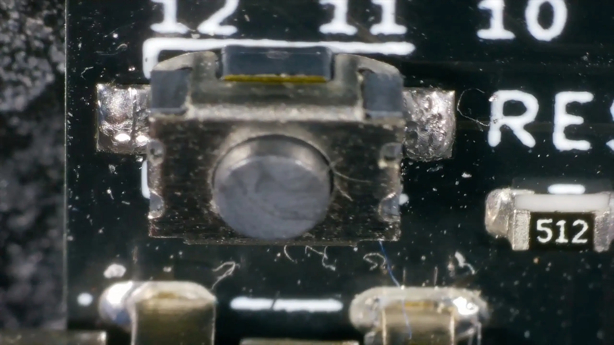
Under the Microscope

Time for a closer look. Under the microscope, the soldering on the ESP32’s EN pin looks fine — which the continuity test already confirmed. The RC components look good too.

The button itself? It looks solidly soldered. Visually, I couldn’t see any obvious problems. Comparing it with the boot button, the boot button’s joints were a bit shinier, but nothing that would explain a total failure.

It’s funny how boards look under the microscope — from a distance, this board looks perfectly clean, but zoom in and there’s all sorts of hairs and disgusting stuff.

Yuck

Reflow and Test

With no obvious visual fault, I decided to reflow the solder joints on the reset button. Applied some flux, heated up each joint, and could feel solid connections on both sides of the switch.

Buzzed it out again. Still nothing. The button clicks mechanically, but there’s no electrical continuity when pressed.

At this point, it’s clear: the button itself is the problem.

The Fix: Just Add Alcohol

Looking more closely, the inside of the button seemed to be full of flux residue. On a whim, I soaked the board in IPA (isopropyl alcohol) to try and clean it out.

After a good soak, I probed the button again — and it worked perfectly. Every press gave clean, reliable continuity.

Plugging the board back in, the blink sketch was running. Hit the reset button and… the flashing stopped. Success!

Lesson Learned

The whole problem was flux residue inside the tactile switch, preventing the internal contacts from making a clean connection. The solder joints were fine, the traces were fine, the schematic was fine — it was just a dirty button.

A remarkably simple fix in the end. A bit of cleaning was all it needed.

The lesson? Use more alcohol — that’s the conclusion I’m taking from this…

Related Posts

ESP32 Rainbow QA - A tale of three boards - We’ve shipped a few hundred ESP32 Rainbow boards-most are perfect - but a few failed QA. Here’s how we tracked down and fixed three real-world faults: no sound from lifted headphone jack pads, USB not enumerating due to a mis-seated ESD IC pin, and a flaky touch keyboard from poor ESP32 module joints. A bit of microscope work and reflow brought two boards back to life (one’s now a donor), and it’s a great reminder why we do final assembly and full QA here in Scotland.
When “Software Bugs” Are Actually Bad Soldering - A quick MLX90640 IR camera test turned into a dead-on-I2C mystery. I ran the usual checks—addresses, pull-ups, voltages, wiring—and even fixed my forgotten UART/I2C jumper, but still nothing. A peek under the microscope revealed sketchy solder on the 3V3 LDO; a quick reflow and the sensor sprang to life. Lesson relearned: don’t trust factory soldering, look early with a microscope, and stop blaming software when the hardware’s silent.
ESP32-S3 Dev Board Assembly - I finally assembled our ESP32-S3 dev boards—used a stencil for easy SMD work, fixed a few tiny USB solder bridges with flux, and even hand-built one for fun. The EPAD isn’t required (per the datasheet), power LEDs look good, and on macOS you can spot it under /dev before flashing. A quick boot-button dance and the blink sketch runs great—full build and walkthrough in the video.
Red Arcade Thing Repair - I resurrected a dead AliExpress arcade handheld by swapping the blown 3.3V regulator (I now own 99 spares), adding a TP4056 charger with Schottky diode isolation, and nursing a 0V LiPo back to life. A bit of hot-plate rework, tidier wiring, and—flip the switch—boom: it boots! It’s not pretty, but it’s alive again.
I broke it and then i fixed it - Started off on a techie adventure with an RP2040 DVI board from Adafruit, aiming to get the pico-zxspectrum going. Things started acting haywire once the USB hub got involved, ending in a complete shutdown, intuitive diagnosis showed the power pin was a ghost town! After pin-pointing (and removing) the dead IC, I performed a delicate soldering operation to bless it with a new 3V3 regulator. Working the kinks out with the resolution led to a thrilling revival and, voila, we were back in business with DVI output and SD Card support!

Related Videos

Why This ESP32 Reset Button Didn’t Work - Had a slightly annoying issue: one ESP32 dev board’s reset button did nothing while the LED kept happily blinking. Schematic and PCB layout were fine, EN net buzzed out, but there was no continuity across the reset switch. Reflowing didn’t help; under the microscope the joints looked good. The culprit? The tactile switch was gunked up with flux. A soak in IPA brought it back to life—continuity restored, reset works, programming mode good. Moral of the story: sometimes it’s not the design—just clean it. Use more alcohol.
I Spent Hours Debugging My Software… - Quick bench update: I tried to get a 32×24 pixel IR module talking over I2C and it just would not play ball—pull-ups, library swaps, address scans, nothing. First silly mistake was not bridging the I2C jumper. Even after fixing that, still dead. Under the microscope I spotted the real issue: poorly soldered pins on the IC. A quick reflow and some IPA cleanup later, it sprang to life. Moral of the story: if yours won’t talk, check the underside soldering. Project video coming soon.
I Built My Own ESP32-S3 Board… And It Actually Works! - I finally assembled my super simple ESP32‑S3 dev board—voltage regulator, reset button, three status LEDs (5V, 3.3V, and a GPIO blinker), and all pins broken out. I showed two build methods: stencil + hot-plate reflow (quick, with a few USB bridges to clean up) and full hand-solder under the microscope, complete with the rigorous ‘solid’ test. Soldered the ESP32‑S3 module (skipping the center thermal pad unless you need it), plugged in, got power LEDs, confirmed USB enumeration, flashed a blink sketch, and we’ve got a blinking LED. Next up: turning this basic dev board into something more professional for production.
Three ESP32 Rainbow Boards Failed QA — Can we fix them? - I’m assembling another batch of ESP32 Rainbows: PCB house does the boards, UV silkscreen and some parts, and I finish assembly and QA here in Scotland. I run through three QA fails—no sound, dodgy keyboard, and no USB—then fix two: the audio fault was lifted pads on the headphone jack, so I bodged it back with flux and solder (speaker and headphones now work, but it’s a spares board). The no‑USB issue was an ESD protection IC sitting off its pad; I reflowed it on a mini hot plate, cleaned up with IPA, verified continuity, and it now enumerates and flashes perfectly. On to the keyboard next—oh, and Happy New Year!
The Devil’s Package - SOT666 - I tracked some QA failures on my ESP32 rainbow boards down to the USBLC6 ESD IC in a SOT666 package—under the microscope the part wasn’t actually landing on the pads. Reflowing fixed it, but that shouldn’t be necessary, so I compared KiCad’s SOT666 footprint to the ST datasheet and found big mismatches. Turns out “SOT666” isn’t consistent across vendors (KiCad/Nexperia/Diodes/EasyEDA all differ), so the only safe move is to follow the exact datasheet for the specific part. I built a new footprint in KiCad per ST’s land pattern, tweaked the routing, and the 3D preview looks good—fingers crossed the next run nails it.
HELP SUPPORT MY WORK: If you're feeling flush then please stop by Patreon Or you can make a one off donation via ko-fi
Want to keep up to date with the latest posts and videos? Subscribe to the newsletter
Blog Logo

Chris Greening


Published

> Image

atomic14

A collection of slightly mad projects, instructive/educational videos, and generally interesting stuff. Building projects around the Arduino and ESP32 platforms - we'll be exploring AI, Computer Vision, Audio, 3D Printing - it may get a bit eclectic...

View All Posts