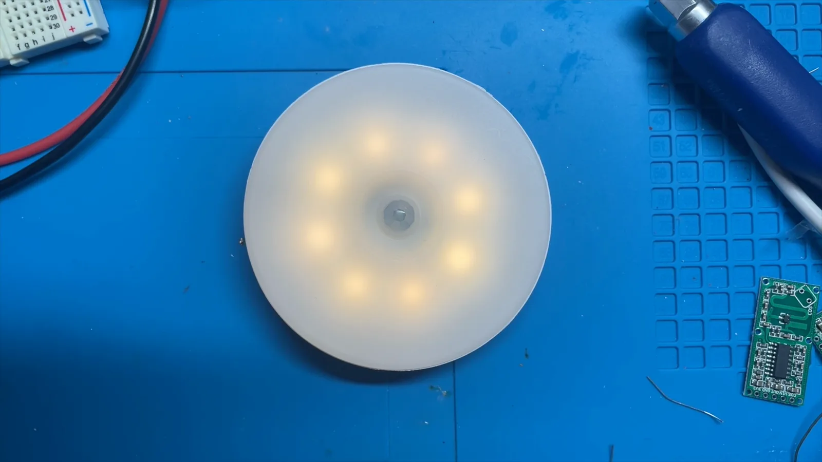
I’ve been picking up a whole bunch of these motion sensitive night lights and, let’s just say, they haven’t been great. The range is poor, the battery life is nowhere near the advertised “charge it four times a year”, and the timeout is so short it’s not even enough time to get to the toilet.
I thought it might be interesting to crack one open and see if I could improve it.
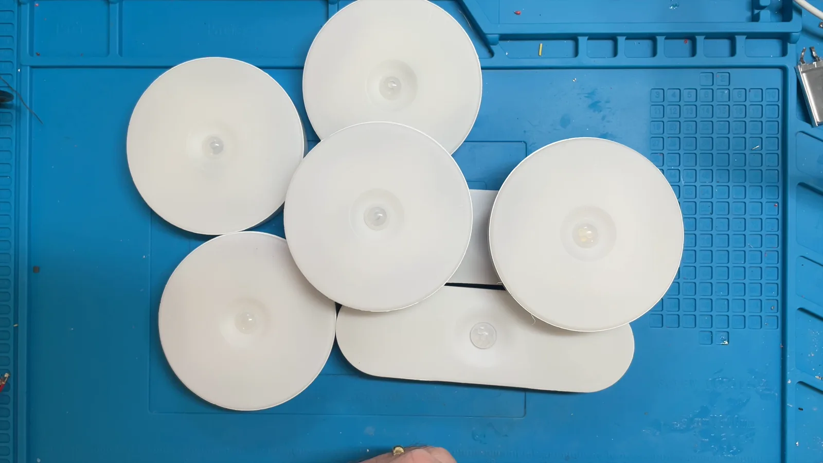
I’ve got both flavours — round ones and oval ones — and internally they’re basically identical, so whatever I do to one should work for both. (Those are affiliate links — if you pick a pair up through them, I get a few pennies at no extra cost to you.)
The Plan
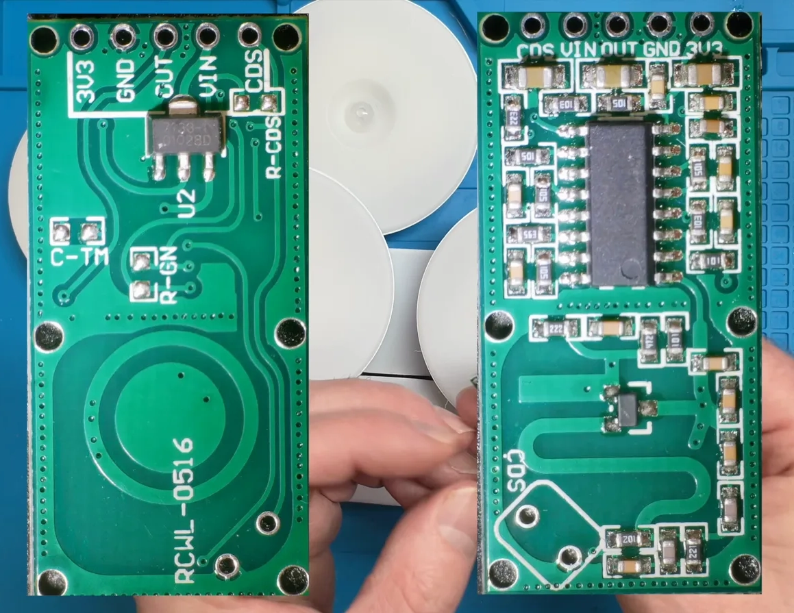
I’ve got a drawer full of these nice little RC-WL0516 microwave radar sensors. They’re much more sensitive than a PIR, they see through plastic, and you can tweak the sensitivity and timeout with a couple of passives. The idea is to rip the original motion sensing front end out of one of these night lights and drop the radar module in instead.
Going down the radar rabbit hole? The modern mmWave modules (HLK-LD2410 and friends) can detect you sitting still, not just moving — I've compared the whole family plus PIRs in my presence sensor guide, and there's a filterable table of all the sensors people wire to ESP32s.
Cracking One Open
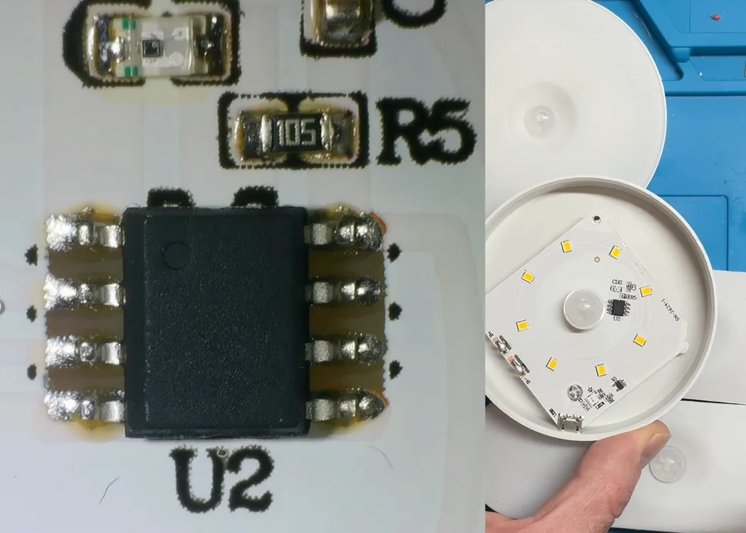
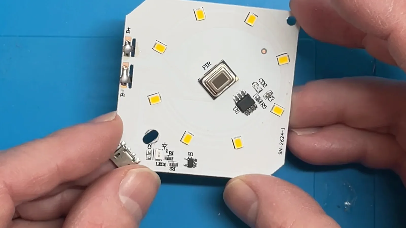
The top just pops off with a bit of a squeeze. Inside, there’s a PIR sensor, an eight pin mystery chip with all the identifying marks sanded off, a light dependent resistor, and some charging circuitry.
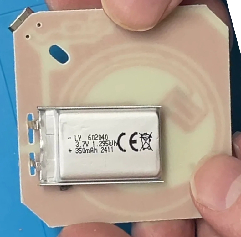
Popping the single screw out releases the board. Underneath is a tiny 350 mAh lithium cell — and no sign of a protection board on it, which is always reassuring.
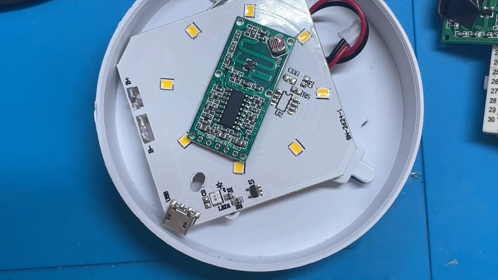
With the board out, the layout is pretty clear. PIR sensor dead centre, ring of LEDs around it, mystery chip off to one side next to the LDR, and the charging circuitry tucked down by the micro USB port.
Doing a Big Clive
Time to do my best Big Clive impression and reverse engineer the circuit. It’s a single layer board, so it’s all quite tractable — the positive side of every LED is tied straight to battery plus, and the negative side goes through the mystery chip down to battery minus.
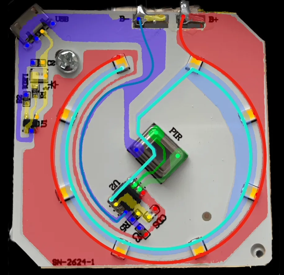
The PIR plus and PIR minus pins go straight into the mystery chip. The LDR is part of a potential divider with R5 feeding another pin on the chip, with a decoupling cap on the rail. Over on the charging side there’s a TP4054 with a 3.3k programming resistor — that’s about 300 mA of charge current — and an LED to show the state. That’s it. Highly optimised BOM, one big mystery IC doing all the work.
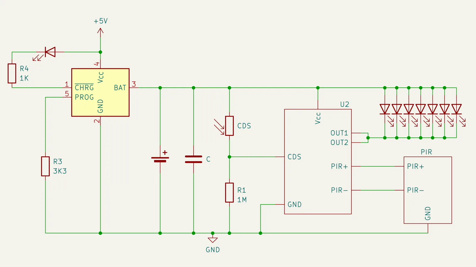
What’s interesting is there’s no current limiting on the LEDs. Nothing at all. The chip is clearly driving them directly, and presumably there’s some limit built in to the chip itself.
How Much Current?
Before doing anything else, I wanted to know how hard this thing is actually driving the LEDs. Desolder the battery, hook the pads up to a bench supply with the current limit set to 100 mA, and trigger the PIR.
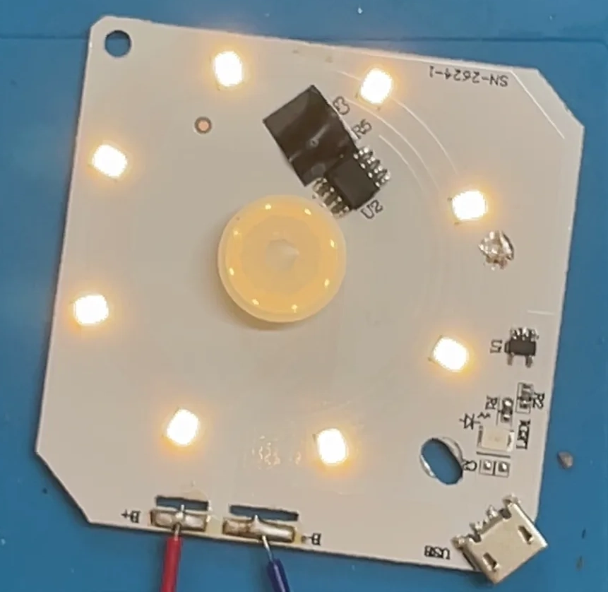
68 mA. So there is some built-in limiting on the mystery chip after all. This mystery IC is doing a lot of heavy lifting.
Playing with the Radar Module
These RC-WL0516 modules are lovely. They have pads for a light dependent resistor so they only trigger in the dark, and a space to solder on a capacitor to extend the timeout.
I wired one up on a breadboard, hung an LED off the output through a current limit resistor, and fed it 5 V.
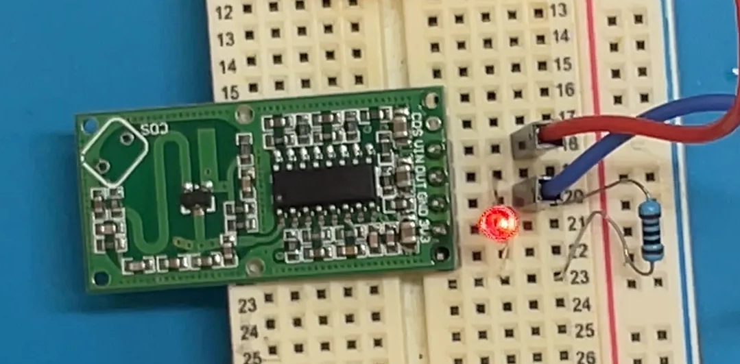
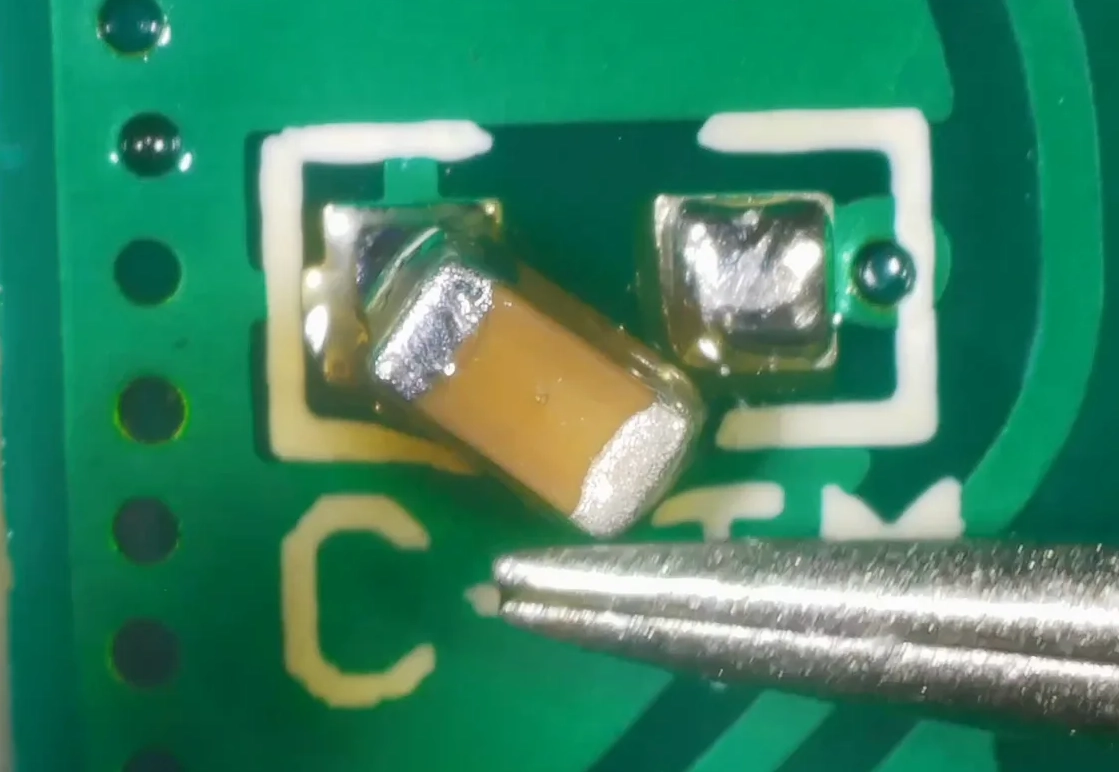
Stand still, the LED goes off. Move, it comes back on. The default timeout is about three seconds. As I mentioned, three seconds is nowhere near enough time to get to the toilet, so I soldered a 0.22 µF capacitor to the CTM pad to extend it.
Much better. I also wired up an LDR so it only triggers in the dark, and confirmed the motion detection works really nicely — much more sensitive than the original PIR ever was.
The Modification
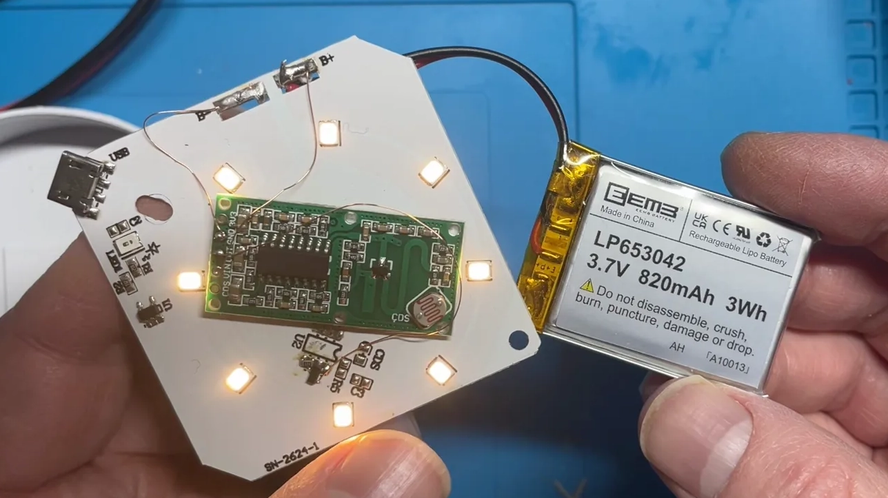
Here’s the plan. Strip the PIR sensor, the mystery chip, and its supporting passives off the original board. Sit the radar module on top where there’s a nice flat empty space. Drive the LEDs through a current limiting resistor and a small MOSFET controlled by the radar module’s output pin. Power everything from the existing battery pads.
Microscope out, and with a bit of soldering the whole thing came together more neatly than I expected. I took the opportunity to upgrade the battery too — swapping the tiny 350 mAh cell for a much more generous 820 mAh one.
The board slides back into its case, the battery tucks in alongside, the USB port still lines up with the hole in the shell, the screw goes back in, the diffuser clips in, and… good as new. You’d never know anything had happened.
Does It Actually Work?
Stuck it on the stairs, turned the lights off, and waited. Walk past — it lights up. Stand still — it goes out after a sensible amount of time. Sensitivity is miles better than it was, the battery should last a lot longer, and the timeout is long enough to be useful.

It works. Now I just need to do the rest of them…
If you want to see the whole thing in motion — the teardown, the reverse engineering, the soldering, and the moment it finally lights up on the stairs — go and watch it on YouTube. Likes and subscribes are always appreciated.