🌈 ESP32-S3 Rainbow: ZX Spectrum Emulator Board! Get it on Crowd Supply →
View All Posts
read
Want to keep up to date with the latest posts and videos? Subscribe to the newsletter
HELP SUPPORT MY WORK: If you're feeling flush then please stop by Patreon Or you can make a one off donation via ko-fi

We’ve now shipped a few hundred ESP32 Rainbow boards; most of the boards have worked perfectly - but there are always a few that don’t make it.

We’ve got three units that have failed QA in different ways:

  • One had no sound
  • One had a dodgy keyboard
  • One had no USB connection

None of these were design issues. They were all the sort of subtle manufacturing or assembly faults you only discover once real boards are powered up and tested.

Let’s take a look at each failure, what caused it, and how it can (or should) be fixed.

Manufacturing & QA

The ESP32 Rainbow PCBs are manufactured by PCBWay, who handle:

  • PCB fabrication
  • UV silkscreen printing
  • Partial component assembly

Final assembly, inspection, and full QA are done here in Scotland.

That QA step is important - it’s where issues like these show up before a board ever reaches a customer.

Failure #1: No sound output

Symptom:
The board has been flashed and everything runs correctly, but there is no audio from the speaker.

Debugging

Applying gentle pressure to the headphone jack caused sound to briefly return - which is a strong hint that this is a mechanical or soldering issue.

Root cause

Under the microscope, the problem was obvious:

  • Multiple pads on the headphone jack had lifted
  • Only one electrical connection remained intact
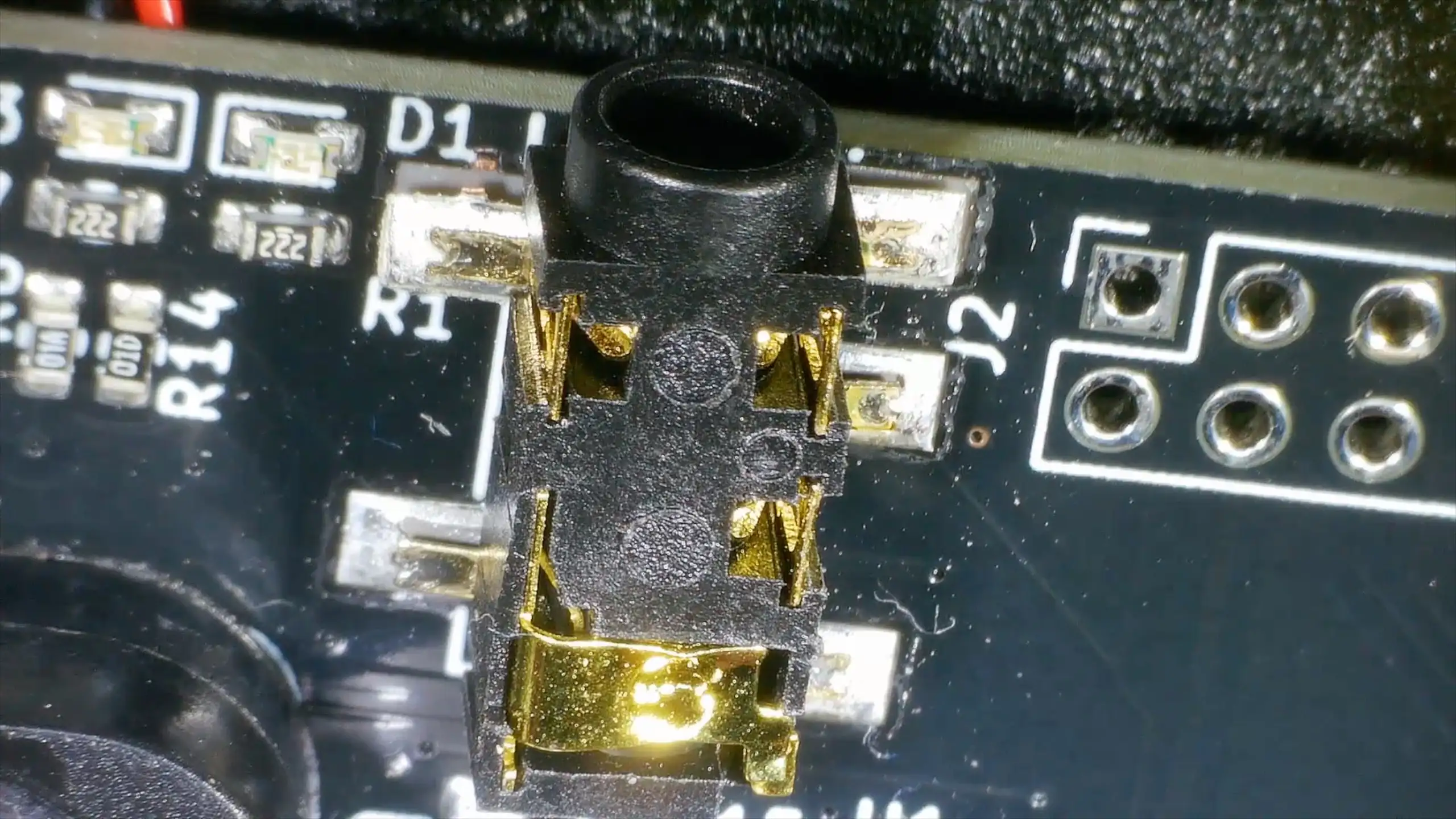
Lifted Pads

This meant the speaker signal was effectively disconnected.

Resolution

This is a reasonably easy fix. We just need to reflow the solder joints, and there’s just about enough copper to reconnect the lifted pads to the ground plane. However, given the damage, this board can’t be sent out to a paying customer - we’ll use it for spare parts.
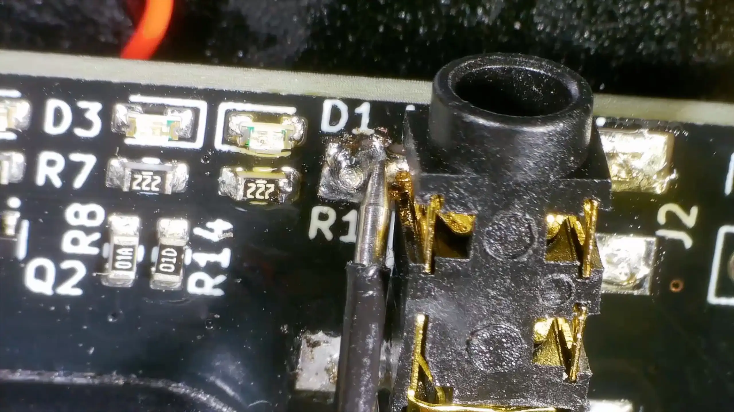
Reconnected

Failure #2: USB not enumerating

Symptom:
The board powers up correctly (3.3 V present), but the ESP32 does not appear over USB.

Debugging

The USB path is fairly simple:

ESP32 → ESD protection IC → USB socket

Using a continuity test, I checked each stage:

  • ESP32 USB pins → protection chip → OK
  • Protection chip → USB socket → OK (?)

Root cause

One pin on the ESD protection IC was not properly seated on its footprint.

Visually it looked almost fine - but one of the pins was not actually connected.
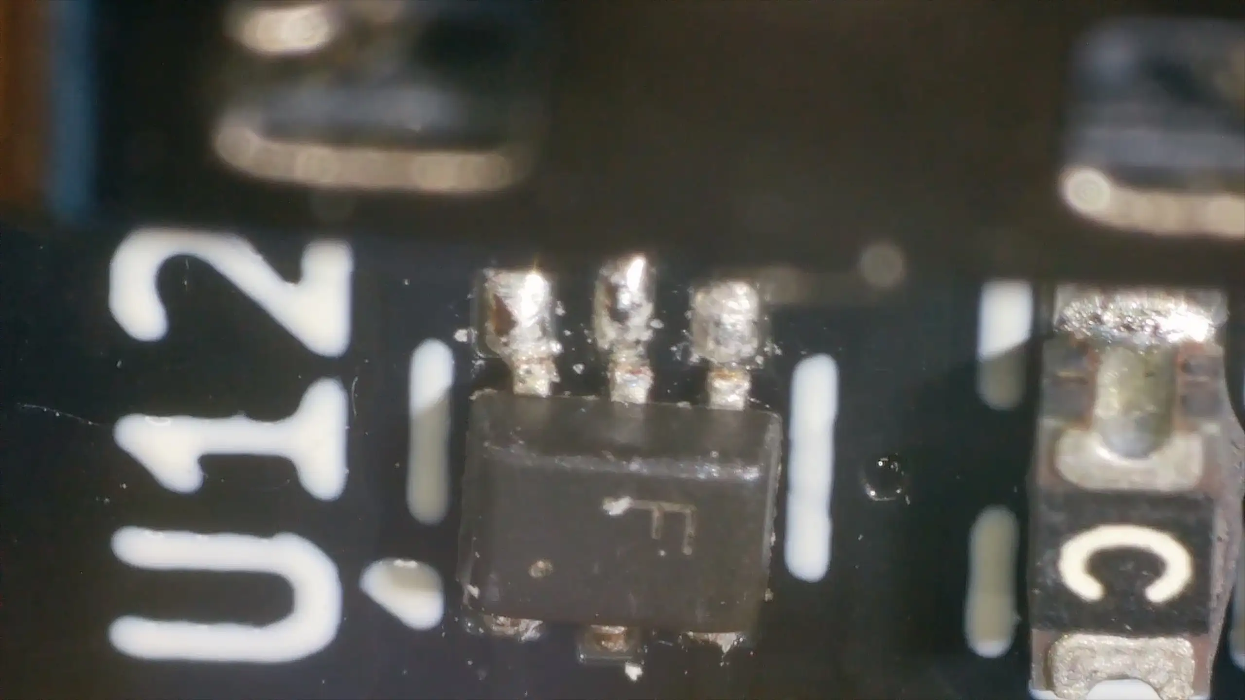
Dodgy ESD Soldering

Fix

Reflow the solder and nudge the IC into the correct position. With that done, we have continuity from the ESP32 USB pins → USB socket.

The board now appears over USB and can be flashed. Everything else works perfectly - we can ship this board to a paying customer.
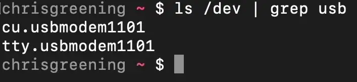
It's alive!

Failure #3: Dodgy keyboard (A–G not working; maybe other keys failing as well)

Symptom:
Several keys on the touch keyboard - specifically A through G - did not register correctly. Other keys behave strangely. The ESP32 Rainbow keyboard uses analogue multiplexers connected to the ESP32 module.

Root Cause

  • Several pins along the bottom of one ESP32 module had poor solder joints
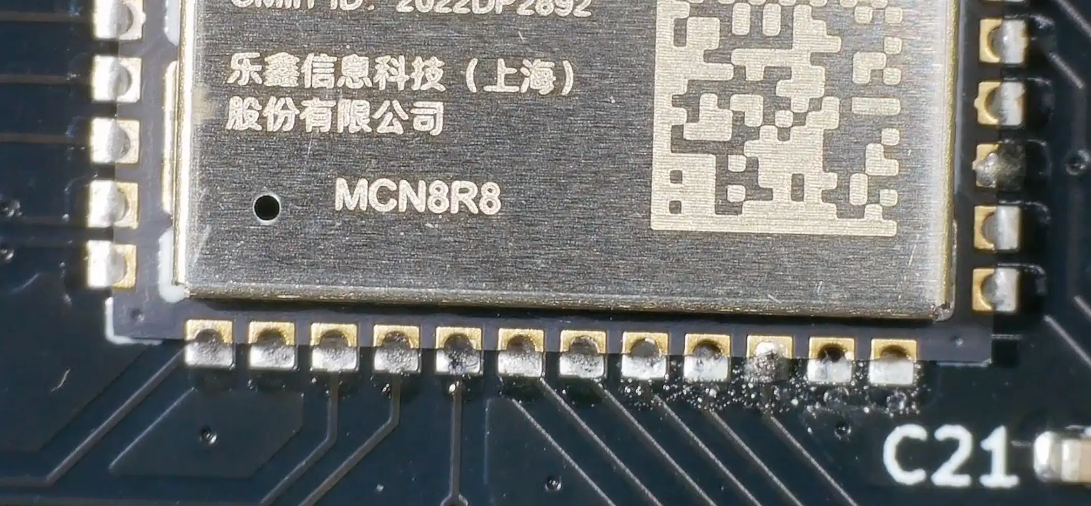
Dodgy ESP32 Soldering

Fix

A straightforward rework:

  • Retouch all the pins with fresh solder

After this, everything works fine - all keys work and the board is fully functional. We can ship this out to a paying customer.
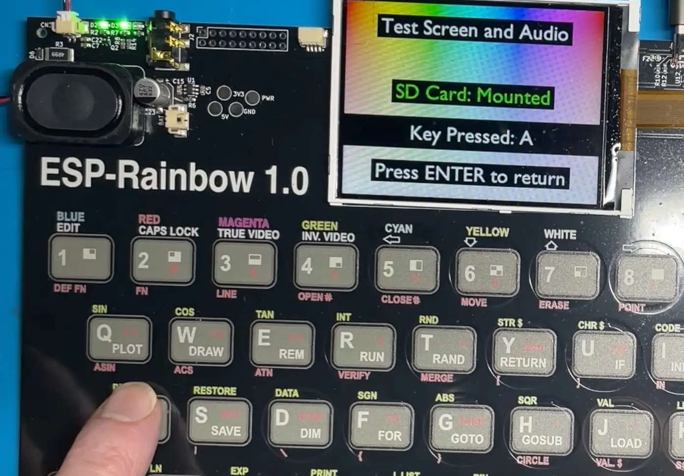
Keyboard Working

Watch the full debugging process

If you want to see the full diagnosis and repair process - including microscope work, probing, and rework - the full video is here:

Related Posts

More fun and games with high voltage - Hey everyone! I know it's been a while since the last video, but things have been crazy busy with shipping off the ESP32 Rainbows. Lately, I've been diving into the world of high voltage again. My last endeavor with a high voltage board led to some gnarly waveforms and flickering LEDs, so I tested with beefy resistors but wasn't thrilled with the results. Fortunately, I've found some nixie tube driver boards that work wonders with LEDs, providing smooth output with little ripple. Still, playing with the old boards has its thrill—hello, 787 volts and some wild sparks! Stay tuned for more high voltage adventures!
ESP32-S3 Dev Board Assembly - I finally assembled our ESP32-S3 dev boards—used a stencil for easy SMD work, fixed a few tiny USB solder bridges with flux, and even hand-built one for fun. The EPAD isn’t required (per the datasheet), power LEDs look good, and on macOS you can spot it under /dev before flashing. A quick boot-button dance and the blink sketch runs great—full build and walkthrough in the video.
ESP32-S3 USB UAC - I turned my new ESP32‑S3 board into a USB Audio device. After a ninja LED fix and confirming the IMU and charging, I streamed mic audio over Web Serial (with a slick AI-made ‘Audio Studio’) and then via USB UAC. The mic sounds great, but the speaker is crackly over UAC—even though I2S WAV playback is perfectly clean. ESP-IDF worked; Arduino didn’t. Bonus annoyance: macOS vs Windows is a toggle, not a combo. Still, this board passes QA.
Why Won't My Board Reset? - One of my ESP32 dev boards refused to reset, even though the schematic, layout, and solder joints all checked out. Continuity was dead across the reset switch, reflow didn’t help, and under the scope it looked fine—until I realized the switch was packed with flux. A soak in IPA cleaned it out and the reset worked instantly. Moral of the story: sometimes the fix really is more alcohol.
ESP32 TV Version 3 - In the latest board revision, I've successfully resolved some key issues, including a USB interface conflict between the USB2244 and the ESP32 and a risky battery charging mistake—no more direct USB 5V to the battery! Plus, I managed to wrap this up without any clumsy bodge wiring. I've even introduced a new feature: a microphone is now on board, setting the stage for some exciting future projects. Stay tuned for what's coming!

Related Videos

Three ESP32 Rainbow Boards Failed QA — Can we fix them? - I’m assembling another batch of ESP32 Rainbows: PCB house does the boards, UV silkscreen and some parts, and I finish assembly and QA here in Scotland. I run through three QA fails—no sound, dodgy keyboard, and no USB—then fix two: the audio fault was lifted pads on the headphone jack, so I bodged it back with flux and solder (speaker and headphones now work, but it’s a spares board). The no‑USB issue was an ESD protection IC sitting off its pad; I reflowed it on a mini hot plate, cleaned up with IPA, verified continuity, and it now enumerates and flashes perfectly. On to the keyboard next—oh, and Happy New Year!
The Devil’s Package - SOT666 - I tracked some QA failures on my ESP32 rainbow boards down to the USBLC6 ESD IC in a SOT666 package—under the microscope the part wasn’t actually landing on the pads. Reflowing fixed it, but that shouldn’t be necessary, so I compared KiCad’s SOT666 footprint to the ST datasheet and found big mismatches. Turns out “SOT666” isn’t consistent across vendors (KiCad/Nexperia/Diodes/EasyEDA all differ), so the only safe move is to follow the exact datasheet for the specific part. I built a new footprint in KiCad per ST’s land pattern, tweaked the routing, and the 3D preview looks good—fingers crossed the next run nails it.
Why This ESP32 Reset Button Didn’t Work - Had a slightly annoying issue: one ESP32 dev board’s reset button did nothing while the LED kept happily blinking. Schematic and PCB layout were fine, EN net buzzed out, but there was no continuity across the reset switch. Reflowing didn’t help; under the microscope the joints looked good. The culprit? The tactile switch was gunked up with flux. A soak in IPA brought it back to life—continuity restored, reset works, programming mode good. Moral of the story: sometimes it’s not the design—just clean it. Use more alcohol.
I Built My Own ESP32-S3 Board… And It Actually Works! - I finally assembled my super simple ESP32‑S3 dev board—voltage regulator, reset button, three status LEDs (5V, 3.3V, and a GPIO blinker), and all pins broken out. I showed two build methods: stencil + hot-plate reflow (quick, with a few USB bridges to clean up) and full hand-solder under the microscope, complete with the rigorous ‘solid’ test. Soldered the ESP32‑S3 module (skipping the center thermal pad unless you need it), plugged in, got power LEDs, confirmed USB enumeration, flashed a blink sketch, and we’ve got a blinking LED. Next up: turning this basic dev board into something more professional for production.
Taking KiCad Silk Screen to the Next Level! - Take a peek at how my ESP 32 ZX Spectrum project is coming along! We're funded on Crowd Supply, ordering components, and adding a cool silk screen design to our PCB. Using tools like KiCad and Affinity Designer, I've jazzed up the back of the board with detailed graphics. It's been an exciting journey, making adjustments and ensuring everything works perfectly before ramping up production. If you haven't yet, head over to Crowd Supply and support the ESP 32 Rainbow project!
HELP SUPPORT MY WORK: If you're feeling flush then please stop by Patreon Or you can make a one off donation via ko-fi
Want to keep up to date with the latest posts and videos? Subscribe to the newsletter
Blog Logo

Chris Greening


Published

> Image

atomic14

A collection of slightly mad projects, instructive/educational videos, and generally interesting stuff. Building projects around the Arduino and ESP32 platforms - we'll be exploring AI, Computer Vision, Audio, 3D Printing - it may get a bit eclectic...

View All Posts