A little while back I ripped the PIR and mystery chip out of one of these cheap night lights and dropped a microwave radar module in its place. It worked beautifully: much better sensitivity, sensible timeout, the whole thing tucked back into the original case like nothing had happened.
But I had a sneaking suspicion I might have improved one thing and quietly ruined another. The radar module is always on. The PIR-and-mystery-chip combo, on the other hand, looked like it was doing something clever with sleep. So before I get smug about my mod, let’s actually measure what each version is pulling from the battery.
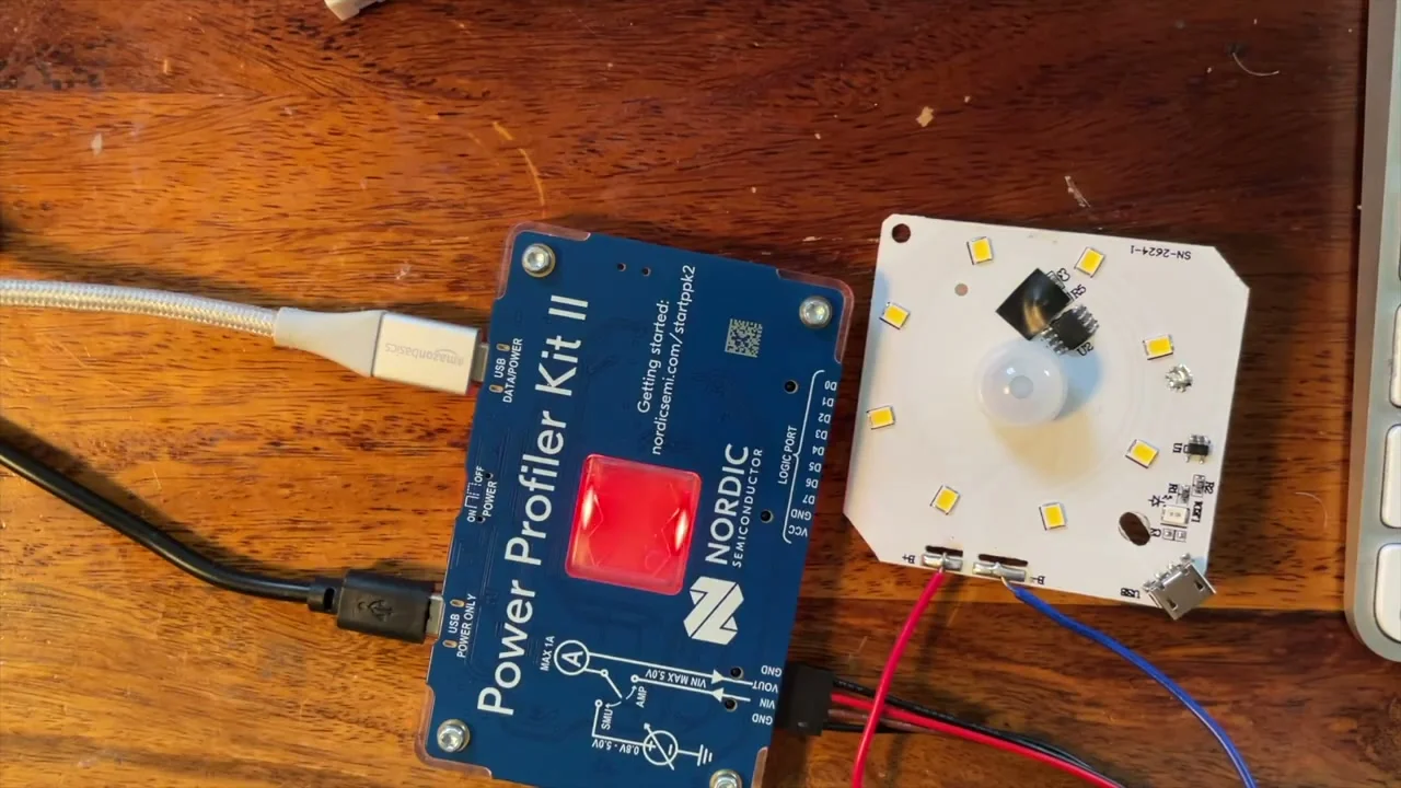
Out comes the Nordic Power Profiler Kit II.
The Original: LEDs On
Power the supply on, start logging, and the LEDs immediately come up to greet me. It takes a moment to actually trigger because I’ve taped over the LDR (the night light flatly refuses to light up unless it thinks it’s dark), but once it triggers we’re sitting at about 80 mA, which matches the last time I measured this on the bench.
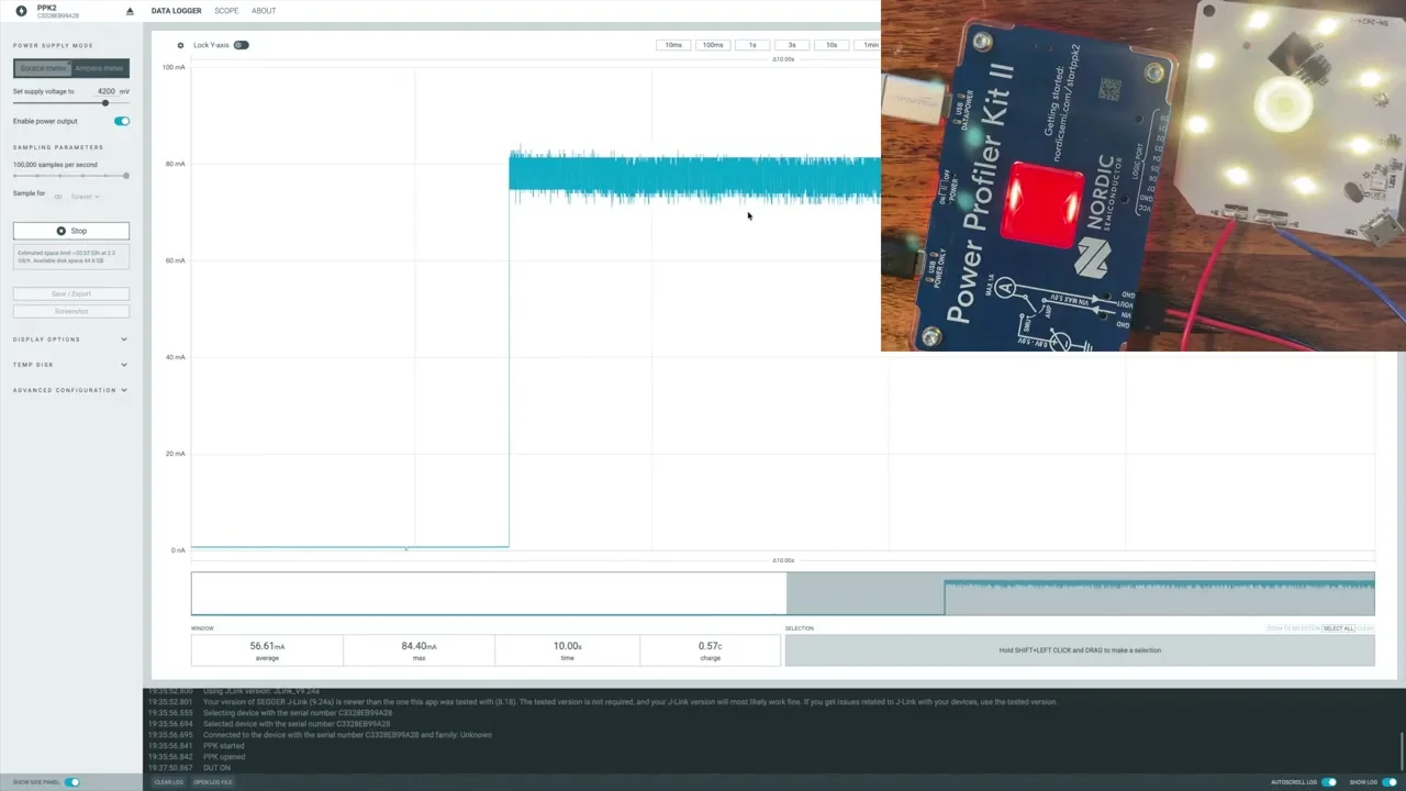
That’s the easy bit. The interesting question is what the board does when it’s not lighting up.
The Original: Waiting Mode
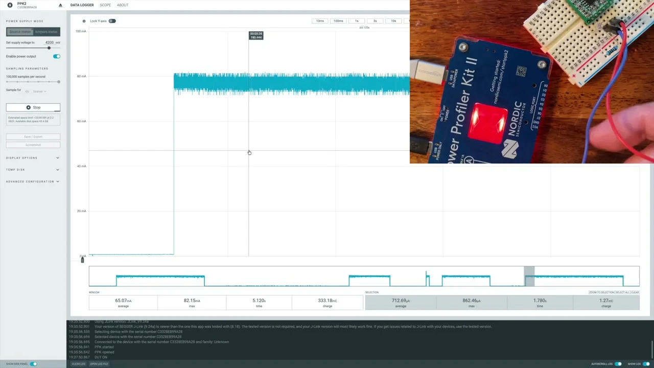
Wait long enough for the LEDs to time out and the trace drops off a cliff. The board settles into a “waiting for movement” mode at roughly 700-800 µA. Fine, that’s basically what a comparator and a small MCU sipping at the PIR signal ought to look like.
But then something weird starts happening. Every so often the trace drops down to a tiny fraction of that. Not lower-by-a-bit. Much lower, about 30 µA.
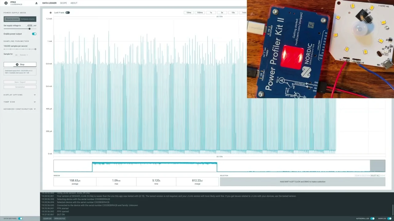
It sits down there for a while, then briefly pops back up to a few hundred microamps, then drops again. It’s clearly a sleep-and-poke pattern: the chip is mostly asleep and only briefly waking up to look at the PIR. As long as I don’t move, it stays in this ultra-low-power mode pretty much indefinitely.
That’s actually really impressive for a chip with all its identifying marks sanded off.
Doing the Maths on the Original
Scroll back to a chunk of the ultra-low-power section, drag a selection across it, and the PPK helpfully spits out the average: 72 µA.
And during the noisier “actively monitoring” segments it’s averaging more like 700-800 µA. So depending on what mood it’s in, the original is sipping between 72 µA and around 0.8 mA. Whichever number we pick, on its 350 mAh cell that’s a lot of standby time. In theory the 72 µA figure puts it at something like 200 days. In practice it definitely doesn’t last that long, but the cell is almost certainly not really 350 mAh either.
The really annoying thing is that I already know from living with these things that the original barely triggers. So all that lovely low power gets wasted because the night light isn’t actually on when you want it to be. Which is, you know, the entire point of a night light.
My Mod: On the PPK
Swap the leads onto the radar version. There’s a current limit resistor in series with the indicator LED here so I don’t have to worry about the LED itself drawing a lot.
Wait the ~40 seconds for the radar’s extended timeout to expire (that big cap on the CTM pad is doing its job) and then we get to see the real story.
My Mod: Idle Current
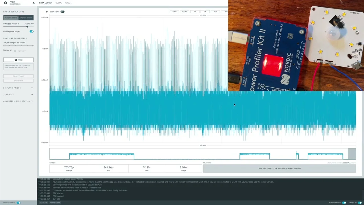
LED out, no movement, just sitting there waiting. The trace settles into a fairly fat band of noise centred around 2.85-2.9 mA.
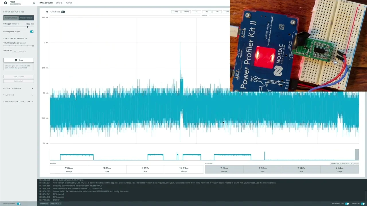
I tried covering and uncovering the LDR to see whether the radar module was doing anything clever with it. Does it actually shut down in daylight, or just gate the output? Spoiler: it just gates the output. The module itself draws the same ~2.86 mA whether the LDR thinks it’s bright or dark. The LDR is purely there to stop the LEDs lighting up during the day, not to save power.
Honestly, 2.8 mA isn’t that bad for a radar module that’s continuously transmitting and listening. It’s just a lot more than 72 µA.
So… Did I Make It Worse?
Time to be honest with the numbers.
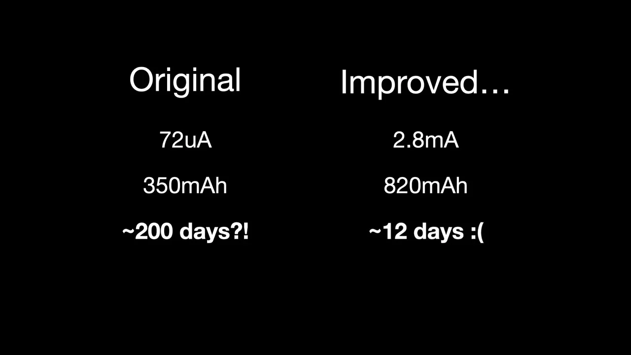
On paper, the original on its sad little 350 mAh cell at 72 µA average should run for around 200 days. My “improved” version at 2.8 mA on the 820 mAh cell I fitted comes out at… about 12 days.
Ouch.
In fairness, the original definitely doesn’t get anywhere near 200 days in real life, partly because the cell is optimistic and partly because every actual trigger spends time at 80 mA. And my mod actually triggers reliably, which the original conspicuously does not. But still, twelve days between charges is rubbish for something that’s supposed to live on a wall.
Salvaging It
All is not lost. I’ve got a stash of much beefier 2000 mAh cells that physically fit inside the case if I’m a bit careful about packaging.
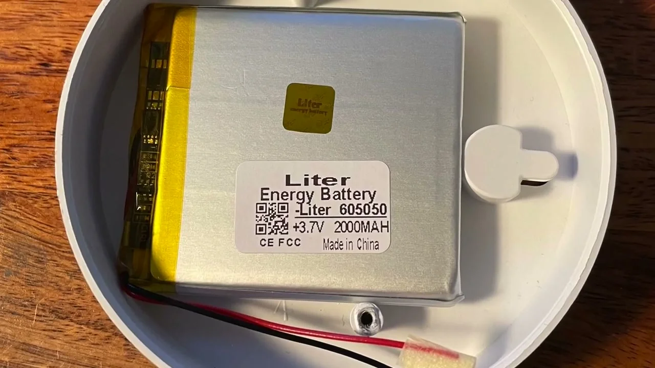
Swapping that in gets the modded version to roughly 30 days between charges, which is much more like it. Not as flashy as “charge it four times a year”, but I’ll actually believe 30 days from a thing that genuinely turns on when I walk past.
So yes: strictly on standby current, I made it considerably worse. But factor in “does it actually do its job”, and a bigger cell, and I think I’m still ahead. Just.
The bit that’s still nagging at me is the original. Whatever that mystery chip is doing in its sleep mode is really nicely done; 72 µA average is properly low. If I could find a way to make the original trigger reliably, I’d have basically the perfect night light. That’s probably a project for another day.
If you want to watch the meters in motion (including the satisfying moment when the trace drops to a pancake-flat 30 µA), it’s all on YouTube.